
CHAPTER 1 · FMC / TFM / PCI Level 2
The Crossover: What Changes and What Stays
In this chapter · 11 sections
Learning outcomes
After completing this chapter, the learner should be able to:
distinguish acquisition, reconstruction, display and interpretation;
define full matrix capture, total focusing method and phase-coherence imaging without using the terms interchangeably;
map a familiar UT or PAUT examination onto an advanced-imaging workflow;
identify the physical principles that transfer unchanged from UT and PAUT;
identify controls and assumptions that require new verification;
explain why a calculated ultrasonic image is evidence rather than a photograph; and
state when a technician must stop and refer a decision to the authorised technical authority.
The bridge from familiar methods
A technician crossing from UT Level 2 or PAUT does not start again at zero. Sound still leaves a transducer, travels through material, interacts with boundaries and returns as an electrical signal. Time of flight still supports location. Wavelength still affects resolution. Reflector orientation still controls whether energy returns to the receiving aperture. Coupling, surface condition, attenuation, noise and geometry can still decide whether useful data are acquired.
What changes is the way the array is excited, the amount of pairwise information retained and the stage at which focusing is applied. Conventional pulse-echo UT usually presents a small number of live A-scans. PAUT applies calculated delays to an active aperture and forms selected beams or focal laws during acquisition. FMC commonly excites selected elements in sequence and records signals on multiple receive elements. TFM then uses a defined acoustic model to calculate a value at each pixel in a reconstruction region. PCI uses phase-coherence information rather than conventional amplitude summation in the implementation addressed by this course.
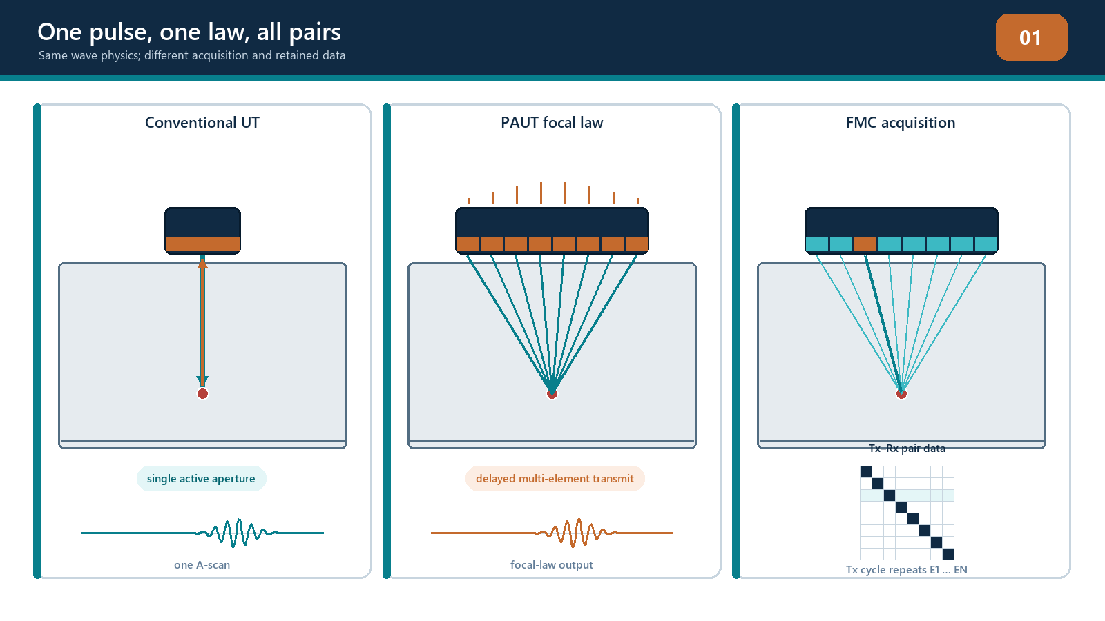
The methods belong to the same ultrasonic family, but they are not interchangeable setup names. A probe capable of FMC has not automatically produced a TFM image. An FMC file has not automatically been reconstructed with the correct mode or geometry. A bright PCI response has not automatically identified a crack. Each stage adds assumptions that must be declared and tested.
The four-stage model
Use four questions whenever an advanced image is presented:
How was the ultrasonic data acquired? Identify the probe, wedge or coupling arrangement, transmit sequence, receive aperture, digitisation, filters, scan position and retained data.
How was the image reconstructed? Identify the material and wedge velocities, component geometry, path family, aperture, region of interest, pixel grid, pair selection, weighting and algorithm.
How was the result displayed? Identify the signal representation, envelope or phase treatment, normalisation, colour scale, threshold, dynamic range and any smoothing or resampling.
How was the result interpreted? Confirm the assumed path, component coordinates, geometry responses, corroborating views, sizing method, uncertainty and governing acceptance source.
These stages prevent a common failure: treating everything visible on the screen as if the probe directly measured it in that form. The instrument measures waveforms. The image is calculated from those waveforms using a model. The technician then interprets that image using inspection knowledge. Confusing the stages makes troubleshooting nearly impossible because a weak or displaced response may originate in acquisition, reconstruction, display or interpretation.
Core terminology
Full matrix capture
In a conventional pulse-echo FMC sequence, each selected element transmits in turn while the selected receive elements record A-scans. The result is a set of transmit-receive traces. A complete square matrix using the same N elements for transmission and reception can contain up to N x N traces at one acquisition position. Some instruments use half-matrix, sparse, multiplexed or otherwise reduced schemes. Those approaches may be useful, but they should be named honestly and shown to meet the examination objective.
FMC describes the acquisition record. It does not specify which image will later be made from the record.
Total focusing method
TFM reconstructs an image within a declared region. For each candidate pixel, the processor predicts the travel time from a transmitting element to that pixel and from the pixel to a receiving element, using the selected path and velocity model. Samples from usable pair traces are aligned and combined. The calculation is repeated over the reconstruction grid.
The phrase focused at every point is convenient shorthand, not a performance guarantee. The focusing is calculated only for the pixels, aperture, path and model that have been selected. True spatial resolution is controlled by the acoustic field, wavelength, bandwidth, aperture, geometry and processing, not by how small or attractive the pixels appear.
Phase-coherence imaging
In the amplitude-free PCI method addressed by this manual, the processor uses the phase coherence of the elementary A-scans for the selected TFM path rather than their conventional amplitude sum. Amplitude information is discarded by that processing route. The method can make diffracting features and crack tips conspicuous, but the displayed coherence response is not echo amplitude in decibels or percentage full-screen height.
Other coherence methods can retain amplitude and apply coherence as a weighting factor. Their controls and output are not automatically identical to amplitude-free PCI. The instrument, software version and documented processing method must therefore be identified.
Crossover map
| Familiar UT/PAUT concept | Advanced-imaging counterpart | What transfers | What needs fresh evidence |
|---|---|---|---|
| Pulse-echo A-scan | One transmit-receive matrix trace | Timing, waveform quality and noise judgement | A pixel may combine many traces |
| PAUT focal law | Pixel-specific reconstruction delays | Delay alignment creates reinforcement | Reconstruction depends on the selected model and path |
| Active aperture | Selected transmit-receive pairs | Aperture affects resolution and sensitivity | Reduced matrices and pair exclusions change performance |
| Sectorial or linear image | TFM reconstruction region and view | Coordinates and geometry remain essential | A pixel grid is not a swept physical beam |
| DAC, TCG and reference sensitivity | Amplitude-domain verification where applicable | Reference targets remain useful | No automatic transfer to amplitude-free PCI |
| PAUT scan plan | Acquisition plan plus reconstruction plan | Coverage must be demonstrated | Each mode and path needs a physical rationale |
| Setup file | Acquisition configuration plus reconstruction recipe | Revision control remains essential | Algorithm and software version become part of traceability |
The three layers of evidence
An ultrasonic event exists in the component whether or not the instrument presents it clearly. The first evidence layer is the acoustic interaction: reflection, scattering, diffraction, transmission or mode conversion. The second is the recorded waveform: a sampled electrical representation affected by the probe, wedge, coupling, electronics and acquisition settings. The third is the calculated display: a selected transformation of many recorded values.
A strong conclusion should be capable of moving back down the evidence chain. If an image response is reported at a particular coordinate, the technician should be able to state the assumed path and identify supporting signals or complementary views. If the path is impossible for the geometry, a colourful response does not rescue it. If raw channels are clipped or absent, later processing cannot recreate the lost information.
This does not mean every production review requires manual inspection of every pair A-scan. It means the technique and review process must preserve a route to the underlying evidence when results are uncertain, contradictory or significant.
A field workflow for advanced imaging
1. Define the examination problem
Confirm the component, material, thickness range, surfaces, weld profile or relevant geometry, expected discontinuity orientations, required coverage, access restrictions and governing acceptance source. Do not begin by choosing the most impressive display mode.
2. Define the acoustic model
Record the probe and wedge geometry, coordinate origin, velocities, interfaces, surfaces and path families. Decide whether the model assumptions are valid for the material. Curved, anisotropic, heterogeneous or strongly attenuating components may need specialised modelling and additional demonstration.
3. Define acquisition
Select the matrix or other acquisition sequence, transmit and receive apertures, sampling, time range, filters, scan increment and data retention. Confirm the instrument actually stores the information required for later review.
4. Define reconstruction and displays
Select justified TFM paths, regions, grids and processing. If PCI is used, identify the implementation and its display scale. Preserve amplitude and raw-data evidence when the procedure or interpretation requires it.
5. Demonstrate performance
Use suitable targets to confirm coverage, position accuracy, relevant resolution, repeatability and response behaviour throughout the intended examination region. Equipment calibration alone does not demonstrate that a multi-view technique can detect and size the target conditions.
6. Acquire and quality-check data
Monitor coupling, channel health, encoder position, scan coverage, saturation and file integrity. Perform required pre-use and post-use checks. Reacquire data when the measurement is invalid; changing the colour scale is not a repair strategy.
7. Interpret and corroborate
Locate each response in component coordinates. Test the assumed path. Compare raw traces, amplitude views, PCI views and complementary modes as applicable. Exclude geometry and processing artefacts before characterisation.
8. Report and retain
Separate observed evidence, interpretation, sizing and acceptance. Record limitations and unexamined areas. Retain the acquisition file, reconstruction settings, software version, annotated evidence and report under the applicable quality system.
Authority and approval boundary
This manual develops understanding and supervised practical ability. It does not itself authorise a technician to select a production technique, approve a deviation, invent acceptance limits or declare a new method qualified. Those responsibilities are assigned by the employer's written practice, approved procedure, governing construction or product code, contract and quality system.
The technician should stop and seek direction when:
the component or material is outside the demonstrated range;
the required path cannot be modelled or physically justified;
acquisition data are clipped, incomplete or not traceable;
verification fails or cannot be repeated;
amplitude and coherence outputs contradict each other without a defensible explanation;
a sizing method is outside its demonstrated limits;
the acceptance source is missing or ambiguous; or
a setup change exceeds an approved essential-variable range.
Escalation is not failure. Continuing without a valid basis is failure wearing a hard hat.
Practical 1 - Build the crossover map
Objective
Classify the stages of an advanced-imaging examination and expose assumptions carried over from UT or PAUT.
Resources
a conventional UT setup summary;
a PAUT setup summary;
an FMC acquisition summary;
one amplitude-TFM image and one PCI image from documented teaching data; and
the blank crossover worksheet.
Method
Without viewing the answer sheet, sort each supplied parameter under acquisition, reconstruction, display or interpretation.
For each UT/PAUT parameter, mark it as transfers directly, transfers with conditions or does not transfer.
Identify the evidence needed to verify every item marked conditional.
Trace one displayed response backward from report statement to image, reconstruction assumptions, contributing data and acoustic path.
Write two circumstances in which the technician must stop and escalate.
Required evidence
completed four-stage parameter table;
annotated crossover map;
one evidence-chain trace; and
a short statement correcting three initial misconceptions.
Stop rules
Stop and ask the instructor if the dataset identity, coordinate convention, path label or display domain is not declared. Do not guess whether a scale represents amplitude or coherence.
Successful completion
The learner correctly separates FMC acquisition from TFM reconstruction, distinguishes amplitude-TFM from PCI, and identifies an authorised acceptance source as separate from the method.
Common traps
Calling the complete method "TFM" without describing acquisition. A reconstructed image may come from full, reduced or other data. The distinction affects performance and traceability.
Assuming more views always mean better coverage. Every extra view adds interpretation opportunities and artefact paths. Use the smallest justified set that demonstrates the required coverage.
Treating image smoothness as resolution. Interpolation can make a display smoother without adding acoustic information.
Treating PCI percentage or colour as amplitude. The domains are different unless a controlled implementation explicitly establishes otherwise.
Believing software removes the need for UT knowledge. The processor applies the model it is given with impressive loyalty, including when the model is wrong.
Chapter summary
FMC, TFM and PCI build on familiar ultrasonic physics but separate the examination into more visible acquisition, reconstruction and processing stages. FMC records pairwise data. TFM reconstructs pixels using predicted travel times for a selected path. Amplitude-free PCI evaluates phase coherence rather than conventional echo amplitude. None of these stages independently proves coverage, defect type, size or acceptance. A defensible result connects the displayed response to a valid acoustic path, sound data, demonstrated technique performance and an authorised acceptance source.
Study and revision only. This is not an approved inspection procedure, acceptance criterion or qualification.