
CHAPTER 12 · Phased Array Ultrasonics Level 2
Manual and Encoded Data Acquisition
In this chapter · 15 sections
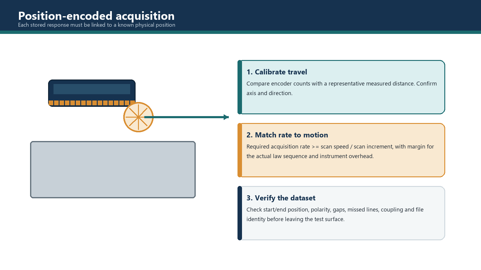
This chapter explains how ultrasonic responses are associated with probe position and how that positional evidence is verified. Its purpose is to help the learner choose between manual and encoded acquisition, calibrate an encoder, control scan speed and recognise when a polished image contains incomplete or wrongly positioned data.
Learning outcomes
After completing this chapter, the learner should be able to:
- distinguish manual scanning from position-encoded acquisition;
- compare common encoder and scanner arrangements without assuming that all encoders use the same sensing principle;
- explain what an encoder measures and identify slip, backlash and mechanical decoupling risks;
- perform a vendor-neutral encoder calibration and polarity verification over a representative distance;
- distinguish encoder resolution, acquisition increment, position accuracy and display pixel size;
- relate scan speed and acquisition increment to the required complete-law-set rate;
- estimate a simple available acquisition rate from aggregate PRF and total sequential law count using stated assumptions;
- check one-line, raster and clicker/index data for positional completeness;
- respond to overspeed, coupling loss, obstacles and interrupted acquisition without hiding a coverage gap.
Key terms
Manual acquisition: Inspection in which probe position is controlled and interpreted by the operator without storing a continuous position value with every acquisition.
Encoded acquisition: Inspection in which position measurements are associated with acquired ultrasonic data.
Encoder: A sensor and interface that convert mechanical movement or position into signals usable by the acquisition system.
Incremental encoder: An encoder that reports changes in position as pulses or counts from a reference zero.
Quadrature: Two phase-related encoder channels used to determine movement and direction.
Absolute encoder: An encoder that provides a position code referenced to its measuring range rather than only incremental counts.
Encoder calibration: Establishment or adjustment of the relationship between encoder counts and known physical travel.
Polarity: The relationship between physical movement direction and increasing or decreasing recorded coordinate.
Encoder resolution: The smallest nominal movement represented by one encoder count under the configured scale.
Acquisition increment: The requested distance between stored complete acquisition positions.
Overspeed: Movement faster than the configured system can acquire and store the required data at the requested spacing.
Clicker/index input: A manual trigger used to advance or identify an index line or position in a partly encoded workflow.
Position correction: Use of encoder coordinates, offsets and beam geometry to place data in component coordinates.
12.1 Choosing manual or encoded acquisition
Manual scanning remains appropriate for many detection, evaluation and local examination tasks. The operator moves the probe, watches the response, optimises it and marks or measures the relevant location. This approach can be responsive and efficient, but its record normally depends on the operator's movement, observations and physical position measurements.
Encoded acquisition stores a position relationship with the ultrasonic data. It supports reproducible maps, review away from the component, comparison between views and systematic proof of scan extent. It is particularly valuable for area mapping, long guided scans and automated or semi-automated inspections.
Encoding does not make an examination automatically complete or accurate. The encoder reports its own measured movement. It does not prove that:
- the probe remained coupled;
- the wedge stayed at the required offset and skew;
- the encoder wheel did not slip;
- the scanner frame remained aligned to the component;
- the correct beam geometry was programmed;
- the instrument stored every required law at every position;
- inaccessible regions were covered.
The selection should follow the governing procedure, required record, geometry, access, data volume and consequence of positional error. Manual scanning may be used to investigate a response found in encoded data, while encoded scanning may be required to preserve the systematic coverage record. These roles can complement each other.
12.2 Encoder and scanner arrangements
Record both encoder sensing and its mechanical drive. A rotary incremental encoder may use optical or magnetic sensing and quadrature channels for direction. Its shaft may follow a wheel, axle, gear or chain; perfect counts do not prevent a wet wheel from slipping.
Linear scales, cable-extension devices and motor/drive encoders measure other parts of the motion chain and may introduce alignment, backlash or compliance errors. Absolute encoders report a coded position within their range. Multi-axis scanners and robots add coordinates only when their mechanical model, component alignment and probe reference are correct.
Movement systems range from a freehand encoded wheel and guided one-axis carriage to clicker-index, two-axis, motorised and robotic scanners. Match the system to the Chapter 11 pattern. One encoded axis cannot independently prove an index coordinate unless another controlled mechanism records it.
12.3 What an encoder actually measures
An encoder measures motion at its sensing point, not acoustic-beam location. Counts are converted to travel; polarity and zero place travel on an axis; offsets connect the scanner to the component datum; and the focal law plus wedge, material and geometry place the beam.
An error can scale, shift or mirror the result. Encoder calibration cannot repair a wrong wedge offset, and correct focal laws cannot repair wheel slip. Challenge backlash, compliance, cable pull and wheel lift during scanner qualification and pre-scan checks.
12.4 Vendor-neutral encoder calibration workflow
Encoder calibration establishes the scale between sensor counts and known travel. The exact equipment controls vary, but the measurement logic is common.
Prerequisites
Before calibration:
- identify the input, axis and nominal scale;
- inspect the sensor, drive, cable, guide and mount;
- use the working or a representative surface condition;
- establish a controlled physical distance and measuring reference;
- obtain the required length and tolerance from the governing procedure;
- remove unintended mechanical play where practical.
There is no universal requirement that the calibration distance must be 500 mm. Use the distance required by the controlled instruction or a representative, accurately measured travel that is long enough to expose meaningful scale error within the available geometry.
Calibration steps
- Place the scanner at a marked start, then zero the selected coordinate.
- Move to the accurately established end in the normal acquisition direction.
- Compare indicated and physical travel, then apply the controlled scale adjustment.
- Repeat the full travel, check zero return and test reverse direction if it will be used.
- Check intermediate positions for non-linearity or slip.
- Record distance, readings, directions, surface, scanner configuration and result.
Do not force a pass by repeatedly changing the scale when results are unstable. Variation between repetitions suggests slip, backlash, loose mounting, an unsuitable surface or a damaged encoder. Fix the mechanism before adjusting more digits.
Worked example 12.1 - correcting scale, then testing repeatability
Given: A scanner travels a physically verified 360.0 mm in the positive scan direction. The first indicated travel is 354.6 mm.
Assumptions: The physical reference is suitable for the required accuracy, the scanner follows the same straight path, no count is deliberately reset during travel and the instrument permits a multiplicative scale correction.
Initial comparison: The encoder under-reports the known travel by 5.4 mm. A candidate scale multiplier is 360.0 / 354.6, approximately 1.0152.
Action: Apply the corrected scale using the instrument's approved calibration function. Repeat the full travel, then check intermediate positions at 90 mm, 180 mm and 270 mm. Return to zero and repeat in the reverse direction.
Acceptance: Compare every result with the tolerance in the governing procedure. No universal pass/fail value is invented here.
Interpretation: If the corrected endpoint is acceptable but intermediate results wander or reverse travel differs, do not accept the encoder merely because one final number looks tidy. Investigate slip, wheel eccentricity, backlash, alignment or intermittent counts.
12.5 Polarity, resolution and acquisition increment
Polarity is correct when movement in the declared positive component direction increases the intended coordinate. Verify it physically at a known datum. If the scanner moves toward +S while the display moves toward negative scan position, correct the channel polarity or the coordinate definition before acquiring production data.
Encoder resolution is commonly expressed as counts per unit distance or distance per count. It describes the nominal quantisation of the sensor scale. It is not the same as position accuracy. A high count density cannot remove wheel slip, mechanical play, scale error or a wrong offset.
Acquisition increment is the requested distance between stored positions. It may be several encoder counts. The system needs sufficient encoder resolution to trigger that spacing consistently, but a 0.1 mm count size does not prove that data acquired every 1 mm are located to 0.1 mm accuracy.
Display pixel size is another separate quantity. Software can enlarge or interpolate an image without changing the acquired position spacing. Record the actual acquisition increment and preserve the raw position data needed to assess it.
12.6 Required rate, available rate and overspeed
During distance-triggered acquisition, the complete required law sequence must be collected at each stored position. Travel speed and acquisition increment determine how often those complete position records are required.
Required acquisition rate >= scan speed / scan increment
For this relation:
- required rate is in complete law sets per second;
- scan speed is distance per second;
- acquisition increment uses the same distance unit;
- speed is assumed approximately steady over the interval.
Finer spacing increases the required rate at the same speed. If system capacity is fixed, finer spacing requires a lower permissible speed. An increment alone cannot establish the required acquisition rate because the travel speed is also needed.
A simple theoretical available rate can be estimated from aggregate pulse-cycle rate and the number of sequential laws required at each position.
Acquisition rate <= PRF / N_laws
This simplified relation assumes sequential laws, equal treatment of each cycle, no extra switching or processing dead time, no averaging repeats, no multi-aperture parallelism and no hidden multigroup interleave. Actual available rate may be lower or be scheduled differently. Verify it on the configured equipment with the actual ranges, groups, gates and storage settings.
Display refresh rate is not a substitute for this check. A screen can redraw at a convenient rate while stored complete-law-set positions are produced more slowly.
Worked example 12.2 - proving a proposed scan speed
Given: A scan is planned at 18 mm/s with a 0.6 mm acquisition increment. The setup contains 72 sequential laws. The configured aggregate PRF is 3,600 pulse cycles per second.
Assumptions: The simple PRF division is used only as an initial estimate. The final equipment test includes actual range, groups, processing and storage. Every stored position requires all 72 laws.
Required rate: Dividing 18 mm/s by 0.6 mm gives 30 complete law sets per second.
Simple theoretical available rate: Dividing 3,600 pulse cycles per second by 72 laws gives 50 complete law sets per second before overhead.
Equipment verification: A trial with the final setup demonstrates a stable complete-position rate of 42 sets per second with no dropped-position indication.
Comparison: The required 30 sets per second is below the verified 42 sets per second. At the stated 0.6 mm increment, 42 sets per second corresponds to 25.2 mm/s as a simple upper boundary before any procedural operating margin.
Decision: The proposed 18 mm/s is technically supportable by this rate check, subject to coupling, mechanical stability and the procedure's qualified speed. Do not promote 25.2 mm/s to a working limit without the required margin and validation.
12.7 Detecting incomplete or overspeed data
Overspeed may cause dropped or delayed positions, incomplete law sets, irregular spacing or an alarm. After a trial and each production scan, compare expected and actual position counts, endpoints and spacing; review overspeed status, law/group completeness, plausible scan time and coupling response.
Reacquire incomplete regions under controlled conditions. Do not hide a gap with smoothing or interpolation; any permitted generated pixels must remain distinguishable from acquired evidence. Coupling loss is separate: correctly encoded empty A-scans still represent missing ultrasonic coverage.
12.8 Corrected one-line and raster data
Encoding relates data to a mechanical path; geometric correction uses beam and component information to place responses. A wrong scan scale stretches indication length even when ultrasonic time calibration is correct. Raster data also need the correct index line, whether supplied continuously or by a controlled clicker.
Correction depends on probe, wedge, velocity, focal law, surface geometry, offsets and polarity. Check a known physical feature before relying on coordinates, and inspect the underlying A-scan and raw positions when a view appears displaced or suspiciously smooth.
12.9 Clicker and manual-index workflows
A clicker workflow continuously encodes the scan axis and uses a manual event to advance the index line. Define index origin and signed increment, line count, direction pattern, event timing, scan-axis reset/reversal behaviour and recovery from a missed or double event.
Use a line checklist and confirm the displayed index at every transition. Stop immediately if an event is wrong; otherwise every later line may shift. At completion, compare stored lines, coordinates and directions with the Chapter 11 plan.
12.10 Stops, obstacles and interrupted scans
An obstacle can break contact, guidance or the relationship between probe and encoder. Stop at the last valid position, identify the affected zone, restart from a datum or verified overlap and reacquire enough overlap to prove continuity. Use a supplementary path where feasible and record any inaccessible volume.
If zero, offset, mounting, orientation or coupling changes, treat the restart as a new controlled segment. Stitch segments using verified common coordinates, not by dragging images until they look convincing.
Field scenario - interrupted encoded weld pass
Situation: A temporary attachment interrupts a guided weld pass and the scanner must be reinstalled beyond it.
Assumptions: Segmented acquisition is permitted, the datum remains accessible and a supplementary path can address the local zone.
Response: Save the first segment with a documented valid endpoint. After reinstalling, verify guide offset, skew, encoder scale and polarity, then begin with controlled overlap. Correlate any supplementary pass to the same datum. Demonstrate segment overlap, local coverage and coupling; report any residual inaccessible volume rather than filling it with fictional ultrasound.
Common traps
- Assuming encoded means automated or complete. Encoding adds position data; it does not prove coupling, alignment or coverage.
- Calling every encoder a potentiometer. Incremental optical, magnetic, absolute and other encoder designs use different principles.
- Calibrating over an invented universal distance. Use the governing requirement or a justified representative measured travel.
- Adjusting scale until one endpoint passes. Check repeatability, intermediate positions and both directions where applicable.
- Confusing encoder resolution with accuracy. Fine counts do not remove slip, backlash or offset error.
- Calculating required rate from increment alone. Scan speed is also required.
- Dividing PRF by one group's laws in a multigroup setup. Count every sequential firing required at each stored position.
- Using display refresh as acquisition proof. Screen redraw and stored complete-law-set rate are separate quantities.
- Hiding missed data with interpolation or smoothing. Preserve the distinction between acquired and generated pixels.
- Treating coupling loss as an encoder problem. Correct coordinates with no valid ultrasound still represent missing coverage.
- Lifting over an obstacle and continuing the same line. Re-establish position and acquire controlled overlap.
Chapter summary
Manual acquisition relies mainly on controlled operator movement and local position measurement. Encoded acquisition associates ultrasonic records with measured positions and supports mapping and later review, but it adds a measurement chain that must be calibrated and checked.
Encoders may be rotary, linear, incremental, absolute or part of a multi-axis scanner. They measure motion at their sensing point, not beam position in the component. Calibration establishes count-to-distance scale; polarity, zero, offsets, mechanical behaviour and focal-law geometry complete the coordinate relationship.
Required complete-law-set rate equals travel speed divided by acquisition increment. A simple available-rate estimate divides aggregate PRF by total sequential law count under restrictive assumptions. Actual capacity must be demonstrated with the final setup. Overspeed, coupling loss, missing index events and obstacles require explicit checks and controlled reacquisition, not prettier interpolation.
Study and revision only. This is not an approved inspection procedure, acceptance criterion or qualification.