
CHAPTER 11 · FMC / TFM / PCI Level 2
Technique Design and Scan Planning
In this chapter · 11 sections
Purpose
A capable instrument does not create a capable technique by itself. Technique design is the controlled conversion of an examination problem into an acquisition plan, reconstruction plan, performance demonstration and reporting route. The process begins with the component and the discontinuities of concern—not with a favourite probe, a maximum number of views or whichever display looks most impressive.
For a Level 2 technician, design work must remain inside the authority granted by the employer’s written practice and the applicable procedure. The technician may prepare calculations, compare options, conduct trials and document evidence. Approval of a new technique, an unqualified path, an acceptance rule or a change outside established limits belongs to the authorised technical authority, normally a Level 3 or another person specifically designated by the governing system.
Learning outcomes
After completing this chapter, the learner will be able to:
translate component, material and discontinuity information into examination and coverage requirements;
select a technically plausible probe, wedge, matrix scheme, scan surface and encoded path;
define a limited set of amplitude-TFM and phase-coherence reconstruction views;
distinguish essential variables, controlled implementation variables and operator conveniences;
select representative targets for technique performance demonstration; and
write hold points, data-retention requirements, approval gates and stop rules.
Crossover map: from PAUT scan plan to reconstruction plan
| Familiar UT/PAUT decision | FMC/TFM/PCI crossover | Evidence required |
|---|---|---|
| Choose angle and probe index to cover the weld volume. | Choose acquisition aperture and physically plausible transmit/receive path families for each required region. | Ray diagrams, sensitivity/coverage evidence and representative reflectors. |
| Set range and gates around expected sound paths. | Set acquisition time range first, then define reconstruction ROIs within recorded and modelled coverage. | Recorded time margin, declared time origin and ROI coordinates. |
| Select an active aperture and focal law. | Define transmit/receive pair population, pair exclusions, aperture and reconstruction recipe. | Matrix audit and controlled configuration record. |
| Set encoded scan increment. | Match encoded increment, scan speed, firing sequence and reconstruction workload without losing positions. | Encoder verification, rate calculation and trial scan. |
| Demonstrate PAUT coverage on a block or model. | Demonstrate each reported path and image domain across the qualified ROI. | Known targets representing location, orientation and difficult conditions. |
| Save an instrument setup. | Control both acquisition configuration and reconstruction/PCI implementation. | Setup revision, software/algorithm version and reproducibility check. |
Start with the examination problem
The technique brief should identify the component before it identifies the equipment. At minimum, establish:
material family, product form and relevant acoustic behaviour;
nominal and permitted thickness range;
weld preparation, cladding, buttering, curvature and accessible surfaces;
datum, scan direction, index direction and component coordinate system;
surface condition, temperature, coating and coupling restrictions;
discontinuity types, likely positions and important orientations;
required examination volume and known unexaminable regions;
required detection, location, characterisation and sizing tasks;
governing procedure and external acceptance source; and
who may approve the technique and any departure from it.
The discontinuity model matters because reflectors do not all return energy in the same way. A smooth lack-of-fusion face can behave specularly and favour a particular incident/receive geometry. A crack tip or small pore may scatter more broadly. A root or cap profile may produce strong coherent geometry responses. Technique design should therefore ask which acoustic interactions are needed, not merely how many images can be generated.
Uncertainty in the brief is itself a control issue. If the actual thickness, weld profile, material velocity range or access condition is not known, record that gap and make it a hold point. Do not quietly replace missing component information with nominal values copied from an unrelated setup.
Select the physical acquisition arrangement
Probe, frequency and aperture
Probe selection balances penetration, bandwidth, wavelength, element pitch, element directivity, physical footprint and available aperture. Higher frequency can improve separation of closely spaced responses in favourable material, but it also increases attenuation and scattering and may reduce usable depth. A larger effective aperture can narrow parts of the point-spread response, while also increasing sensitivity to surface profile, wedge geometry and element directivity at ROI edges.
The selected aperture must fit the access and remain coupled throughout the encoded path. Probe clearance should be checked against cap, attachments, taper, curvature and scanner structure. A model showing an unobstructed probe on a flat plate is not proof that the real scanner can follow the production surface.
Wedge and interface model
Record the wedge identity, nominal geometry, wear allowance, probe mounting, reference point and temperature limitations. For a curved or profiled surface, state how the interface is represented. The ray model may require element-specific entry points and refracted legs. A wedge or surface description that is adequate for a central PAUT law may not be adequate across a large TFM ROI.
The technique should define how wedge delay, element position, index offset and component origin are established and verified. These inputs act together. Adjusting a coordinate offset to conceal an incorrect wedge model may make one reflector line up while degrading the rest of the ROI.
Matrix scheme and raw signal quality
State whether the acquisition is full matrix, half matrix, sparse, plane-wave, virtual-source or another defined strategy. Record active transmitters, active receivers, any excluded pairs, sample rate, time range, gain, filtering, digitisation and averaging. A reduced acquisition can be entirely valid when demonstrated and approved; it must not be called full FMC merely because the instrument reconstructs a TFM-like image.
The gain and range should retain useful RF information without saturation. For phase-coherence processing, “amplitude-free” does not mean “signal-quality-free.” Phase obtained from a noise-dominated, clipped or cross-talk-contaminated trace is not reliable evidence.
Encoder increment and acquisition rate
The encoded increment must support the required along-scan coverage and any qualified length measurement. The instrument must also complete the selected acquisition sequence quickly enough for the planned motion.
required position rate >= scan speed / encoded increment
For example, a scan speed of 60 mm/s and an encoded increment of 1.0 mm require at least 60 valid position records per second. Practical planning adds margin for firing time, storage, display and scanner variation. If the actual valid rate is only 45 positions per second, the choices are to slow the scanner or reduce workload through a controlled, demonstrated change. Allowing silent gaps is not a valid optimisation.
Design the reconstruction set
Choose paths for a reason
Each proposed reconstruction view requires an explicit path diagram showing transmit legs, receive legs, modes, reflections or conversions, surfaces and velocities. Select a small set that addresses the discontinuity orientations and locations in the brief. More views consume processing time and create more opportunities for path ambiguity. They do not automatically increase coverage or confidence.
A useful path-selection record answers four questions:
What feature or region is this view intended to interrogate?
Is the complete transmit and receive route physically possible?
Will the selected aperture transmit and receive useful energy along that route?
Which reference or representative target will demonstrate its performance?
If one answer is missing, the view is an experiment, not a production technique component.
Define ROI and grid
Define the ROI in component coordinates and include only the required volume plus justified margins. Extending a box beyond the weld does not create acoustic coverage. Confirm that the acquisition time range includes every required path with pre- and post-response margin.
Choose grid spacing by demonstrated peak stability, location accuracy, separation performance and workload. Pixel spacing is numerical sampling, not physical resolution. Where amplitude TFM is evaluated, verify that grid placement does not cause unacceptable amplitude variation. For phase/coherence views, verify repeatability and localisation using the actual implementation; do not invent a universal coherence threshold or assume that a finer grid always improves detectability.
Control image domains separately
Amplitude TFM and phase-coherence imaging present different quantities. The plan should identify the amplitude reference, gain, normalisation, envelope and colour range for amplitude views. For a coherence view, record the documented algorithm or product implementation, band/filter, aperture, threshold, exponent or other available controls, and displayed range. A coherence percentage must not be substituted for percentage full-screen height or a DAC/TCG level.
If phase-only processing suppresses a broad interface or backwall response used for coupling monitoring, provide a parallel amplitude channel, conventional PAUT group or dedicated coupling check. A display that hides the evidence needed to verify data quality is not self-sufficient.
Essential variables and approval gates
An essential variable is a parameter whose change can affect coverage, sensitivity, position, resolution, characterisation, sizing or data traceability. Typical candidates include:
component material, thickness, geometry, surface and temperature range;
probe, wedge, frequency, pitch and active aperture;
acquisition type, element population, gain, range, sampling and filters;
encoder axis, increment, direction, scan offset and speed limit;
velocity, wedge/surface model, component origin and thickness;
path family, ROI, grid and pair weighting/exclusion;
amplitude or phase/coherence algorithm and processing version;
display scale where it affects detection or measurement;
performance targets and verification tolerances; and
retained data format and reconstruction recipe.
Not every user-interface preference is essential. Window arrangement and non-evaluative colour preference may be conveniences if they cannot affect the controlled result. The classification must be based on evidence, not on where the setting appears in the menu.
Set approval gates for a new path, a material outside the demonstrated range, an altered probe/wedge, a changed algorithm version, an unqualified sizing method, missing acceptance criteria or a performance failure. A Level 2 may document the issue and propose options. The authorised technical authority decides whether review, re-demonstration, procedure revision or rejection is required.
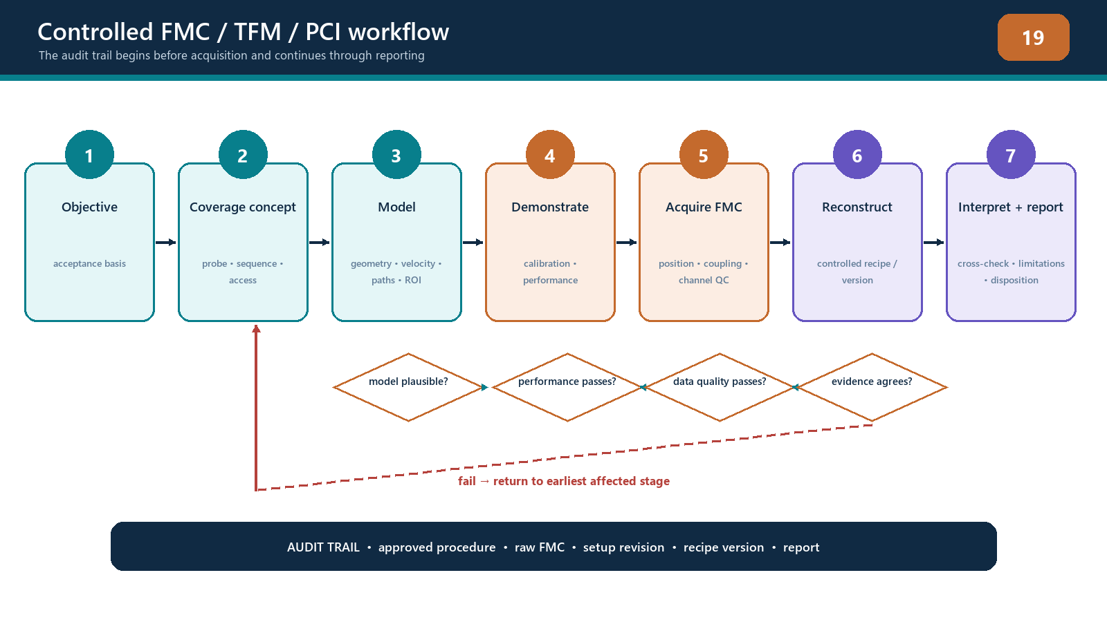
Field workflow: build and freeze the technique
Confirm the inspection objective, governing procedure, acceptance source and approval authority.
Gather controlled component drawings and verify important dimensions on the actual item where required.
Define the discontinuity model, required volume and difficult orientations.
Select the physical acquisition arrangement and draw access/coverage limitations.
Define matrix, sampling, timing, gain, encoder and data-retention controls.
Draw every proposed transmit/receive path and identify the target that will test it.
Set ROIs, grids and image-domain controls with a stated performance objective.
Identify essential variables, limits, hold points and re-verification triggers.
Conduct modelling and trials as planning aids, then demonstrate the complete technique on representative targets.
Freeze approved acquisition and reconstruction revisions; issue the controlled instruction before production work.
Practical 11 — Produce a controlled technique plan
Aim
Prepare a vendor-neutral FMC/TFM/PCI technique plan for a defined weld-like specimen and defend every selected view and control.
Resources
controlled component drawing and examination objective;
stated material and thickness range;
probe, wedge and scanner data;
a documented acquisition/reconstruction capability description;
reference and representative target inventory; and
the organisation’s technique template and approval workflow.
Method
Mark the component datum, scan axis, index axis, accessible surfaces and required examination volume.
List the discontinuity orientations and locations that the technique must address.
Select a probe/wedge and justify frequency, pitch, aperture and physical access.
Define the acquisition matrix, time range, sampling, gain/filter conditions and encoder increment.
Calculate the minimum required position rate for the proposed scan speed and compare it with a witnessed trial rate.
Draw each reconstruction path and limit the set to views with a specific purpose.
Define ROIs, grids, amplitude controls and phase/coherence controls.
Select targets that challenge central, near-surface, backwall-adjacent and orientation-sensitive performance.
Prepare an essential-variable table with permitted ranges and actions outside those ranges.
Add pre-scan, in-scan and post-scan checks, retained-data requirements and report fields.
Record unresolved technical or acceptance questions as approval gates.
Present the plan for Level 3 or otherwise authorised technical review before treating it as a production technique.
Evidence to retain
annotated component and coverage drawing;
path diagrams with modes and velocities;
acquisition and reconstruction parameter tables;
rate and data-volume calculations;
representative-target rationale;
essential-variable and hold-point register;
known-limitations statement; and
dated review comments and approval status.
Stop rules
Stop if the governing acceptance source is unavailable; component geometry or material is materially uncertain; a selected path cannot be drawn physically; acquisition time/rate cannot cover the plan; required targets are not available; software behaviour or algorithm version cannot be identified; or the learner is asked to approve a change outside their authority. Do not convert an unresolved gate into a footnote after scanning.
Common traps
Beginning with the maximum number of views instead of the inspection problem.
Treating modelled coverage as demonstrated sensitivity.
Calling a reduced acquisition “full FMC” without evidence.
Using a large ROI to disguise unsupported edge regions.
Reporting pixel size as acoustic resolution or sizing accuracy.
Assuming PCI removes the need for coupling, gain and signal-quality controls.
Treating a setup file as the entire technique.
Leaving software and reconstruction versions out of essential variables.
Using a convenient side-drilled hole as the only target for a planar-flaw problem.
Importing acceptance criteria from a method standard or another project.
Chapter summary
Technique design connects the component, discontinuity problem, acquisition, reconstruction, verification and report. It requires explicit paths, bounded ROIs, justified grids, adequate scan-position rate and separate controls for amplitude and phase/coherence outputs. A model supports planning; representative targets establish performance.
The Level 2 technician can contribute calculations, trials, scan plans and evidence within authorised scope. New methods, paths, essential-variable limits, sizing rules and acceptance routes require the defined technical approval. A frozen setup is useful only when the complete technique and its evidence are controlled.
Study and revision only. This is not an approved inspection procedure, acceptance criterion or qualification.