
CHAPTER 14 · Ultrasonics Level 2
What Manufacturing Does to the Sound
In this chapter · 21 sections
Why this matters
Two components can carry the same material grade and thickness yet produce very different ultrasonic screens. One plate may give a clean, steady back-wall echo. Another may show structural noise, a weak back wall or responses that change with scan direction. The difference is often the material history: how it was cast, rolled, forged, welded, built, heat treated or damaged in service. A Level 2 practitioner does not need to become a metallurgist. You do need enough process knowledge to choose a sensible probe, recognise a difficult path and avoid calling material response a discontinuity.
What you already need
- Basic pulse-echo and angle-beam paths.
- The ideas of wavelength, attenuation and signal-to-noise ratio.
- How probe movement helps test an indication.
- A simple understanding of plate, weld and corrosion examinations.
What you will learn
- How product form changes both likely discontinuities and ultrasonic behaviour.
- Why scan direction, frequency and reference evidence must suit the actual component.
- How to use manufacturing knowledge without allowing it to predetermine the result.
- How service damage and repairs change the acoustic path.
- How to state a practical material limit in the examination record.
Words you will meet
- Product form: the manufactured type of item, such as plate, forging or casting.
- Grain: a small region of material with a common crystal orientation.
- Anisotropy: behaviour that changes with direction.
- Segregation: uneven distribution of material constituents during solidification.
- Heat-affected zone: parent material changed by welding heat without being melted.
- Structural noise: responses created by material structure rather than the target of interest.
- Attenuation: reduction of usable sound energy along a path.
14.1 Begin with the component, not the alloy name
Before selecting a setup, write down five facts: product form, manufacturing route, heat treatment, weld or repair history, and service condition. Then ask how each fact could affect the expected discontinuities or the sound path. This short check is more useful than memorising a catalogue of metallurgy.
Consider the three recurring jobs in this Part. A rolled plate may contain laminations roughly parallel to its broad faces. A weld may contain lack of fusion aligned with a fusion face, while its solidified structure changes beam direction. A corroded pipe may have a rough back wall, deposits and locally changing thickness. The material designation alone does not reveal any of these measurement conditions.
Manufacturing knowledge is therefore an input to the plan. It suggests where to look, which directions to use and what may limit the result. It is not permission to label an echo without acoustic evidence.
14.2 First look: compare a known path
A practical material check begins with something the screen can show. On an accessible sound region, obtain a stable reference or back-wall response. Note its travel time, amplitude, pulse shape and noise level. Repeat from another position or direction using the same controlled setup. Large, repeatable changes tell you that one simple material model may not cover the whole component.
Keep the comparison fair. Coupling, surface condition, probe pressure, gain, range and path length can change the screen without any change in material. Correct or record these influences before assigning a material cause. A weak back wall on a curved or corroded surface is not automatically high attenuation.
If the job has serious consequences, representative reflectors are stronger evidence than the back wall alone. A back wall proves that some energy returned from that boundary. It does not prove that the system can detect the required target at every position and orientation.
The following figure connects each manufacturing route to the practical response patterns that may need checking.
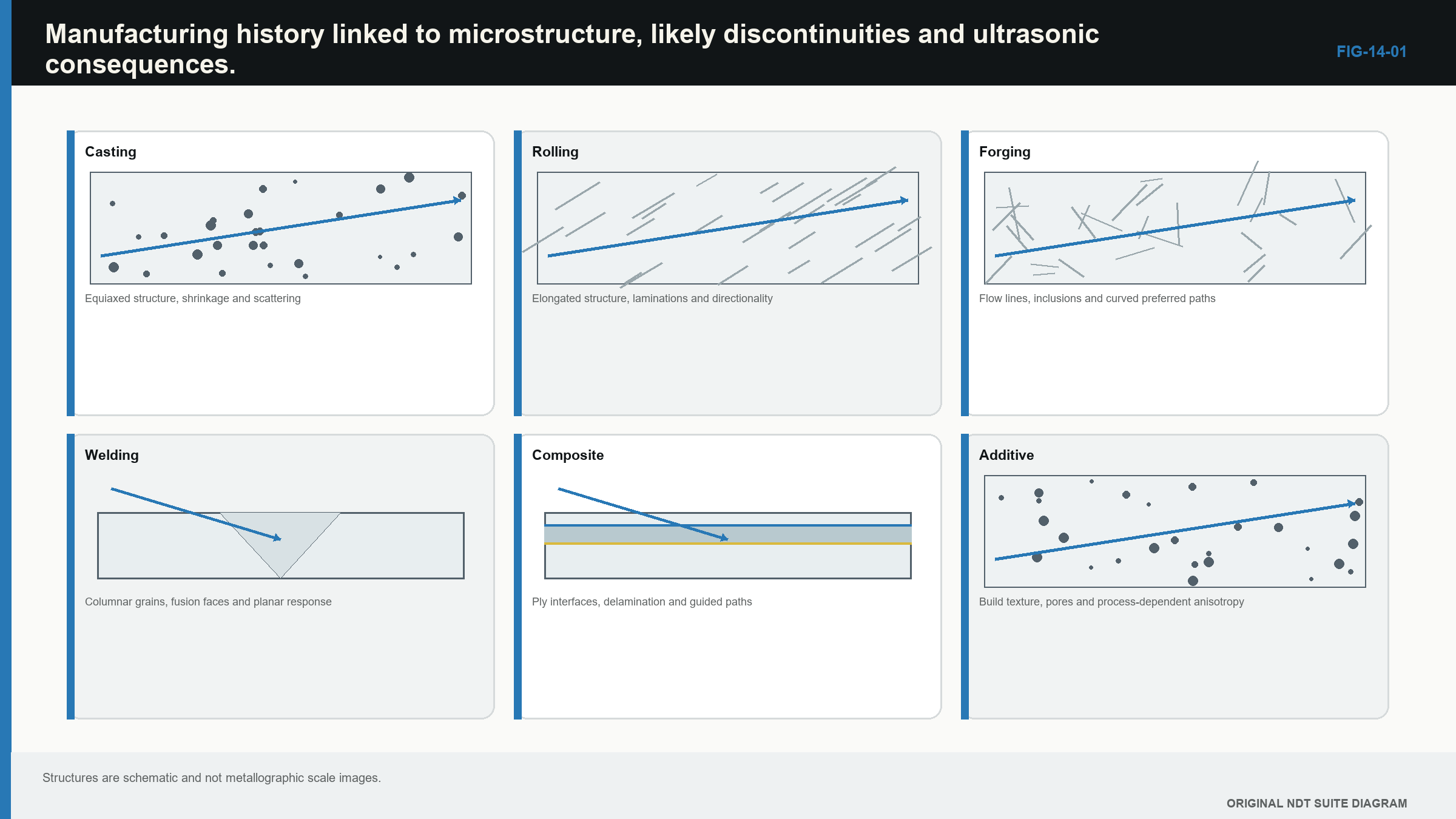
Notice that the process changes both the likely target population and the medium carrying the beam.
14.3 Cast products: expect local variation
A casting solidifies inside a mould. Cooling, feeding and gas control influence grain size, porosity, shrinkage and segregation. Thick sections and changes of section can cool differently, so response may vary across one casting. Column-like grains can also make velocity and loss depend on direction.
For the practitioner, the screen may show a raised grass level, scattered responses, a broad loss of back wall or different penetration at different positions. Those patterns are observations, not final diagnoses. Poor coupling, curvature and a hidden reflector can produce some of the same effects.
Start with a lower frequency if the original setup cannot provide usable penetration, then prove that the longer wavelength and wider pulse can still meet the detection requirement. Coarse-material evidence shows that useful coverage depends on the actual structure and the chosen aperture, not on a universal casting penalty. [R011] [R012]
| Worked example · Choose a starting frequency in a coarse casting WE-14-01 Given: On the same controlled path, a 5 MHz probe gives a back-wall echo 18 dB lower than a 2 MHz probe. Relative to its own reference level, the 5 MHz display also has 12 dB more structural noise. Find: Which probe provides the more useful starting setup for detection on this path. Steps: Compare penetration and usable signal-to-noise ratio. Do not choose by frequency alone. The 2 MHz probe keeps more back-wall energy and shows less relative structural noise. Answer: The 2 MHz probe provides the stronger starting case on this casting path. What it means in practice: The result supports penetration. A representative target must still show whether the 2 MHz pulse and beam can resolve the required discontinuity. Common mistake: Declaring the lower-frequency setup capable simply because its back wall is larger. |
|---|
14.4 Rolled plate: direction and planar reflectors
Rolling compresses and elongates material. Inclusions and separations can become extended in the rolling plane. A normal beam can therefore meet a lamination close to normal incidence and produce a strong response with reduced back wall below it. An angle beam may interact with the same planar feature very differently.
When screening plate before a weld examination, map any lamination rather than recording only its largest echo. Its extent and position may block or redirect a later weld beam. Scan from more than one direction where the examination objective requires it. Rolling can also create directional response, so compare like paths along and across the rolling direction when performance changes unexpectedly.
Grain-scale scattering depends on grain size, orientation and elastic contrast relative to wavelength. [R009] This means structural noise is information about the path, but it is not by itself evidence of a reportable lamination.
14.5 Forgings, extrusions and grain flow
Forging changes shape by working the material and redirects grain flow around the part. It can close some voids and refine structure, yet laps, bursts or poorly worked regions can remain. Extrusion and drawing commonly develop strong structure along the working direction.
A shaft examined radially may not behave like the same shaft examined axially. A reference block cut without regard to product direction may transfer poorly. Record the reference orientation and compare it with the component path. If sensitivity or location changes with direction, treat direction as part of the setup rather than averaging the difference away.
Geometry still matters. A weak or missing echo near a curved shoulder may result from reflection away from the probe. Use another position, path or known geometry response before assigning the loss to the forging structure.
14.6 Weld metal and the heat-affected zone
A fusion weld is a small casting. The fusion zone solidifies from its boundaries, and grain orientation follows the heat flow. The heat-affected zone beside it changes without melting. Weld passes, reheating, repairs and dissimilar materials add further local variation.
Ferritic welds often allow a useful simple path model, although geometry and local structure still affect the echo. Austenitic and dissimilar-metal welds can be strongly directional. Measurements reported for austenitic welds show that velocity and attenuation can change with propagation direction and wave polarisation. [R008] A ray drawn using parent-material velocity may then show a neat path that the main energy does not actually follow.
On the screen, watch for a consistent shift in known reflector position, loss of high-frequency content, broadening and direction-dependent amplitude. Compare opposite scan directions or known weld features where access permits. If the results disagree systematically, record the model limit. Do not change one velocity merely to force one echo into the expected place and then assume every other path is corrected.
14.7 Composite and bonded structures
Composite material is arranged in layers, fibres, resin, interfaces and sometimes a cellular core. Its wave behaviour depends on ply direction, wavelength, architecture, geometry and target type. [R003] A normal beam may respond well to a delamination parallel to the surface while being less informative about cracking parallel to fibres.
Interfaces create repeated echoes and can hide shallow or closely spaced damage. Impact damage can include several mechanisms at once: matrix cracks, delaminations, fibre damage or crushed core. One C-scan, a plan-view response map, does not describe every mechanism.
For Level 2 practice, state which layer, interface or damage orientation the setup is intended to examine. Verify the usable path on representative construction. More advanced composite models distinguish the direction of wave phase from the direction in which energy travels and define when an averaged material model remains useful. [R006] Those models belong later; the immediate rule is to distrust an unverified straight ray in strongly layered material.
14.8 Additive products
Additive manufacture builds the component through repeated thermal cycles. Build direction, scan strategy, surface condition and post-treatment can affect texture and likely discontinuities. Possible targets include lack of fusion, pores and cracks, each with different shape and orientation.
A machined coupon may represent the internal material but not the rough surface of the production item. A coupon made in another build direction may not represent its propagation either. Qualification evidence should therefore match the build and post-processing conditions needed for the claim.
Simulation work also shows that different descriptions of random grain structure can predict materially different echo amplitudes. [R013] Treat a model as a tested aid, not as a replacement for representative evidence.
14.9 Service damage changes the target and the path
Service history tells you which mechanisms are plausible. Fatigue cracks often start at stress concentrations and tend to lie across the opening stress. Corrosion removes and roughens a boundary. Erosion-corrosion can produce directional loss. Stress-corrosion cracking may branch. Creep damage may begin as distributed cavities before linked cracking becomes measurable.
Match the measurement to the mechanism. Thickness mapping suits wall loss. Angle-beam coverage suits many planar cracks. Distributed microstructural damage may require another validated material-characterisation method. Do not turn an ordinary flaw detector response into a material-condition claim that the setup was never designed to support.
Surface and loading conditions can change an existing response. Compression may close a crack and reduce reflection. Deposits or oxide can change an interface. Temperature can change velocity and coupling. When trending an indication, compare those conditions as well as peak amplitude.
The next figure compares common target orientations with candidate beam directions across the recurring plate, weld and corrosion cases.
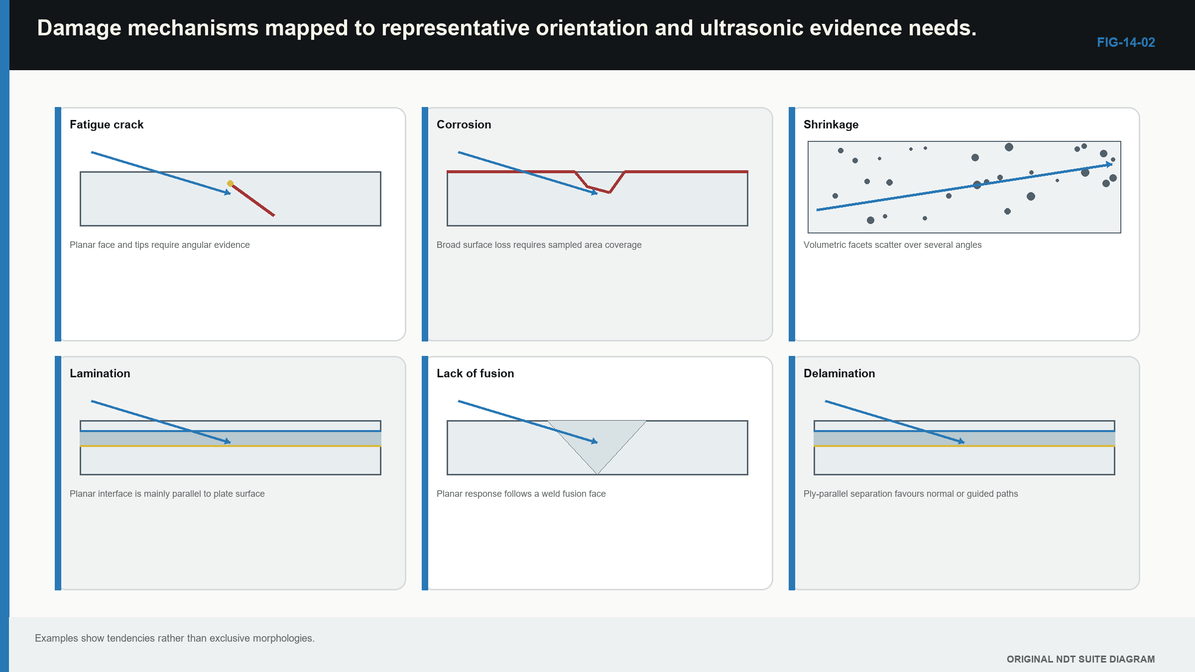
Notice that a beam suited to wall loss is not automatically suited to a planar crack or weld fusion face.
14.10 Repairs create a new local component
Grinding changes surface profile. Weld repair adds another fusion zone, heat-affected zone and residual shape. Heat treatment may change velocity and attenuation. Cladding creates a layered path. After such work, an earlier baseline may no longer represent the same component-system interaction.
Mark repair boundaries on the scan plan and compare sound paths that cross and avoid them. If a known reflector moves only when the beam crosses the repaired area, changed propagation is a strong hypothesis. Check that electronic timing and probe position stayed stable before acting on it.
| Worked example · See the location error caused by a wrong path velocity WE-14-02 Given: The actual velocity along a material path is 5,700 m/s. The instrument uses 5,900 m/s. The measured round-trip time is 30.0 microseconds. Find: The displayed and actual one-way distances. Steps: Distance is velocity multiplied by round-trip time, divided by two. Displayed distance is 5,900 m/s x 30.0 microseconds / 2 = 88.5 mm. Actual distance is 5,700 m/s x 30.0 microseconds / 2 = 85.5 mm. Answer: The display places the reflector 3.0 mm too far away. What it means in practice: Precise timing cannot correct a material model that uses the wrong directional velocity. Common mistake: Adjusting zero until one reflector aligns, then applying that correction to different paths through the material. |
|---|
14.11 Use process knowledge as a clue, not a verdict
Product form creates useful expectations. Rolled plate makes planar laminations plausible. A casting makes shrinkage and coarse structural response plausible. A weld fusion face makes lack of fusion plausible. These expectations guide coverage and interpretation, but the echo must still earn its label.
Use a simple discipline. First state what was observed: time, position, amplitude, shape and change with probe movement. Then list the leading physical explanations. Next perform a check that separates them, such as an alternate direction, frequency, surface or reference path. Finally record the conclusion and its limit.
This prevents two opposite errors. Ignoring manufacturing loses valuable context. Allowing manufacturing to predetermine the answer turns every expected defect into a self-fulfilling signal.
| Worked example · Separate a material-path change from a timing shift WE-14-03 Given: A known reflector appears 1.5 microseconds later when the path crosses a repair zone. The instrument reference timing is unchanged. The echo also becomes broader and loses high-frequency content. Find: The leading explanation category. Steps: Stable reference timing makes a general electronic shift less likely. The delay, pulse broadening and frequency loss occur only on the repair path. Together they support changed velocity and attenuation or scattering in that local material. Answer: A local material-path change is the leading hypothesis. What it means in practice: The repair region needs path-specific verification or a stated location uncertainty. Common mistake: Correcting the display with one zero adjustment and hiding the evidence that the path itself changed. |
|---|
In plain words
- Ultrasonic sound travels through the material that manufacturing produced, not through an ideal grade name.
- Product form suggests likely discontinuities and likely propagation problems.
- A changed screen can come from material, geometry, coupling or the system; control the other causes before deciding.
- Lower frequency may improve penetration but must still meet the detection and resolution need.
- Direction matters in rolled, forged, welded, composite and additive products.
- Repair and service history can change both the target and the path.
- Manufacturing knowledge should guide the examination without deciding the answer in advance.
Key terms
- Structural noise: repeatable material responses that compete with the target signal.
- Grain flow: directional material structure produced by working or solidification.
- Product form: how the item was manufactured, such as plate, forging or casting.
- Repair zone: a local area whose geometry and material history have been changed.
- Representative evidence: a reference path or target close enough to the component conditions to support the claimed capability.
Key relationships
- Shorter wavelength can improve separation, while scattering may reduce usable penetration.
- Directional velocity error becomes a distance or location error on the display.
- A back-wall response supports penetration along that return path; it does not by itself prove detection of every target.
- Material, spreading, interfaces, coupling and directivity can all contribute to observed loss. Their formal dB bookkeeping is relocated to advanced treatment as EQ-14-01.
Common mix-ups
- Material grade is not a complete acoustic description.
- A weak back wall is not automatically high material attenuation.
- Structural noise is not automatically a reportable discontinuity.
- A known manufacturing mechanism is not proof that a particular echo came from it.
- A machined reference coupon does not automatically represent a rough or differently oriented production item.
Bridge to Chapter 15
Manufacturing history becomes especially important at a weld. Chapter 15 combines the weld drawing, likely formation mechanisms and probe movement into a practical way to separate weld discontinuities from roots, caps, fusion faces and other geometry.
Sources and further study
- [R003]
- [R006]
- [R008]
- [R009]
- [R011]
- [R012]
- [R013]
Study and revision only. This is not an approved inspection procedure, acceptance criterion or qualification.