
CHAPTER 10 · FMC / TFM / PCI Level 2
Using PCI and Related Coherence Views
In this chapter · 15 sections
Purpose
Phase-coherence imaging can make small diffracting responses stand out when an amplitude image is dominated by larger specular or geometry echoes. It can also suppress a planar reflector, hide familiar coupling evidence, or produce a strong response from coherent geometry. The responsible use of PCI is therefore comparative: understand the implementation, inspect the source data, and combine phase-domain and amplitude-domain evidence without pretending they use the same units.
This chapter uses PCI to mean an amplitude-free phase-coherence TFM implementation documented by the system provider. Methods that calculate a coherence factor and multiply it by an amplitude image are called coherence-weighted imaging. Both belong to a broader family, but they are not identical and must not share unverified thresholds or performance claims.
Learning outcomes
After completing this chapter, the learner will be able to:
complete an implementation profile for a PCI-capable system;
distinguish amplitude, coherence and coherence-weighted output domains;
compare responses from crack tips, small volumetric reflectors, planar faces and component geometry;
identify processing and display controls that change apparent indication form;
decide when raw signals, amplitude TFM, PAUT or another view is needed for corroboration; and
reject unsupported transfer of DAC, TCG, percentage-FSH or dB-drop rules to a phase-only image.
Crossover map: complementary evidence, not replacement units
| Amplitude-domain practice | PCI/coherence crossover |
|---|---|
| Echo height is compared in volts, percentage FSH or decibels. | A phase-only implementation displays a bounded or normalized coherence-related quantity whose scale is defined by that implementation. |
| DAC and TCG compensate or compare amplitude with path. | They are amplitude-domain tools and do not automatically calibrate a coherence image. |
| Gain changes displayed echo amplitude. | Gain still controls the source receiver data and must avoid noise and clipping, even if phase-only output does not use amplitude as its final metric. |
| A −6 dB or other drop can support authorised sizing. | It cannot be transferred to phase-only PCI without a demonstrated, approved relationship. |
| Strong planar and backwall echoes are familiar reference evidence. | Phase-only PCI may reduce broad specular responses, so a separate coupling or amplitude view may be required. |
| Multiple PAUT angles provide orientation evidence. | Matched amplitude TFM and PCI views can provide complementary face, corner and tip evidence from the same acquisition. |
Three related processing families
Amplitude TFM
The selected FMC samples are delayed and coherently combined. A signed RF result or its envelope/magnitude is displayed. The output depends on source amplitudes as well as phase alignment. Sensitivity, attenuation, transfer, gain and grid amplitude stability remain relevant.
Coherence-weighted amplitude imaging
A phase or sign coherence factor is calculated and used to weight an amplitude reconstruction. In-focus or phase-consistent regions can be retained while less consistent regions are reduced. The displayed result still contains amplitude information, although it has been modified by the coherence weighting. Its units, normalization and threshold rules must be defined by the implementation.
Amplitude-free PCI
The implementation discards amplitude from the final pixel metric and displays phase/sign agreement itself. Some systems may normalize or binarise source samples and use a vector or sign-based process. The result is not an amplitude TFM image with a different palette. It cannot be interpreted using amplitude-response rules unless the governing procedure has independently established a relationship.
The source acquisition may still be ordinary full-waveform FMC, allowing both amplitude TFM and PCI reconstruction. Another implementation could retain only binarised or single-bit information to reduce storage. If amplitude is discarded at acquisition or export, ordinary amplitude reprocessing may be impossible. The data-retention record must say which case applies.
Build an implementation profile
Before using PCI, obtain controlled documentation and record:
system, software and firmware version;
probe, wedge and active element range;
acquisition type: full FMC, reduced matrix, plane wave or other;
whether full RF amplitude is retained;
selected propagation path and aperture;
source time range, sampling, gain and filters;
documented phase/sign/coherence family;
output range, units or unitless scale;
normalization basis;
threshold, colour map, persistence and smoothing;
low-signal handling, if documented;
contributor or sub-aperture rules;
supported ROI and grid controls;
export and reprocessing limitations; and
manufacturer or procedure claims that have been independently demonstrated for the application.
If a setting is inaccessible or proprietary, record that fact rather than inventing its value. A black-box control may be used only inside the capability demonstrated for the controlled version.
Amplitude and coherence answer different questions
Amplitude TFM asks how strongly the delayed waveforms combine in the selected amplitude processing chain. Phase-only PCI asks how consistently their phase or sign agrees according to its algorithm. Neither result alone describes defect severity.
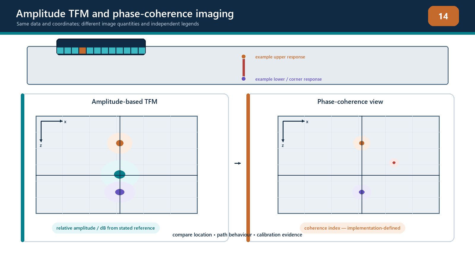
Consider four idealized cases:
High amplitude and high coherence: a strong compact reflector, favourable corner response or coherent geometry may produce both.
Low amplitude and high coherence: a weak but consistent tip diffraction may become prominent in PCI, provided source signals remain above noise.
High amplitude and low all-aperture coherence: a strong planar response may reach only a limited sub-aperture, or overlapping modes may disturb phase.
Low amplitude and low coherence: this may be background, poor coupling, excessive attenuation or an unsupported path.
These combinations show why brightness cannot be translated directly between views. PCI may show two bright tip points while amplitude TFM shows a face or corner. That does not mean one image is correct and the other wrong; they may be emphasizing different scattering evidence.
Expected target behaviour
Small volumetric and point-like reflectors
Small targets can scatter over a broad angular range and support many transmitter–receiver pairs. Both amplitude TFM and PCI may show a compact response. A side-drilled hole remains an extended cylinder with directional and mode-dependent behaviour; do not call it a universal point target.
Crack tips and notch ends
Tips can diffract weak, broadly distributed energy. A phase-only view may increase their contrast relative to large specular echoes and background. Tip-to-tip distance can support sizing when the tips are correctly identified, spatial performance is demonstrated, and the written procedure authorises the method.
A pair of bright points does not automatically prove one continuous crack. Separate small reflectors, mode artifacts or geometry can mimic tip pairs. Confirm path, movement, intermediate evidence and complementary views.
Smooth planar reflectors
A smooth face returns energy specularly. Only a subset of the aperture may share a strong common response. Phase-only PCI can under-represent or fragment the face even when amplitude TFM shows it clearly. This is a known limitation of the response domain, not permission to disregard the amplitude evidence.
Backwalls and component geometry
Broad surfaces may be reduced in PCI relative to diffracting features. This can improve visibility close to a large interface. It can also remove familiar evidence of coupling, thickness and surface position. Maintain an authorised amplitude, A-scan or dedicated coupling monitor.
Where phase evidence fails
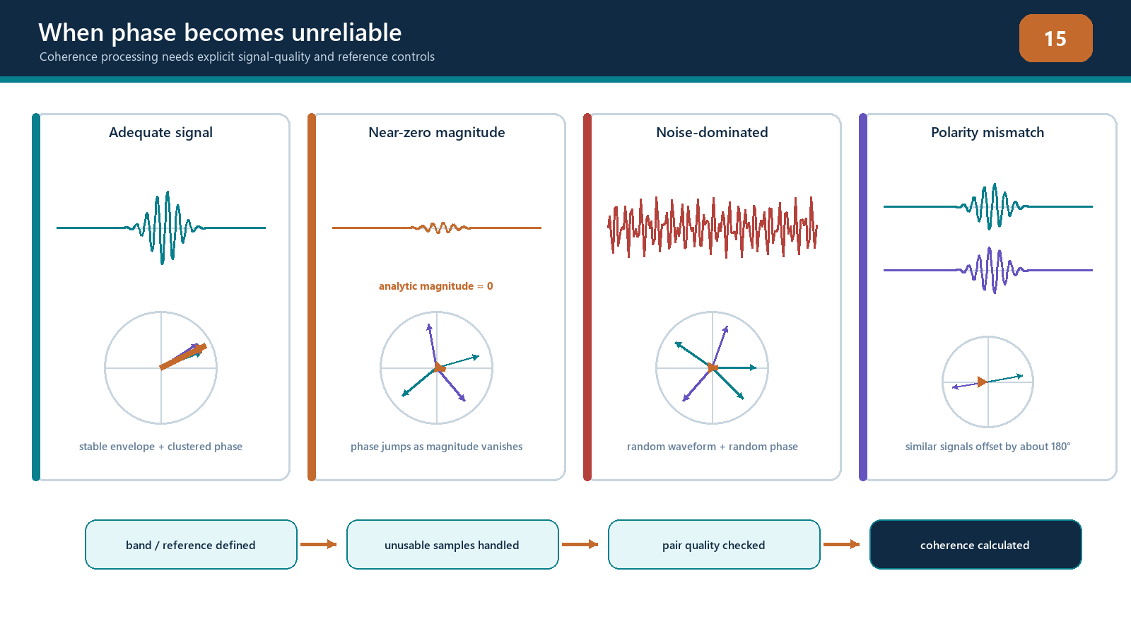
Insufficient source amplitude
Phase is only meaningful while the recorded waveform contains usable signal. Beyond penetration, after severe attenuation or under poor coupling, normalization can turn noise into unit phasors. A bounded display may still produce local speckle. Check raw amplitude and repeatability.
Clipping and saturation
Clipped RF loses waveform shape and can create false phase stability or instability. An amplitude-free final metric does not excuse source clipping. Set gain to preserve the required dynamic range, then verify small-target response.
Timing and model mismatch
Wrong velocity, wedge delay, surface profile, path or element position leaves residual phase error. PCI can suppress a real response that an amplitude view still shows, or place coherence at a false solution. Check localization on reference targets throughout the ROI.
Coherent noise
Cross-talk, ring-down, repeated interface reverberations and encoded acquisition artifacts can be phase consistent. If a response is fixed to instrument time, transmitter number or wedge position rather than component coordinates, treat it as suspect.
Limited aperture support
A high score formed from a small sub-aperture may have different meaning from one supported across the full useful aperture. Inspect contributor distribution where the implementation allows it, or use raw pair data to infer support.
Display manipulation
Threshold, normalization, colour map and smoothing can turn a diffuse coherence field into isolated hot spots or conceal weak ones. Use fixed settings for comparison and retain an unprocessed or baseline view.
Gain and the phrase “no amplitude calibration”
Some amplitude-free PCI implementations do not need an amplitude reference curve for the final coherence scale. This limited statement must not become “PCI needs no calibration.”
The complete inspection still needs:
equipment and element checks;
time zero, wedge and component velocity verification;
encoder and coordinate verification;
path and ROI validation;
source-signal dynamic range and coupling control;
reference-target detection and localization;
phase/coherence performance demonstration;
sizing validation where used;
software/version control; and
a procedure-approved evaluation basis.
Gain remains important because it determines how the analogue signal is presented to the digitiser. Too little gain can leave the target in receiver noise. Too much can clip large responses. A suitable phase-only display does not rescue either condition.
Sizing and evaluation boundaries
Do not apply:
DAC or TCG curves;
percentage-FSH thresholds;
transfer corrections in decibels;
amplitude comparison with reference reflectors; or
−6 dB, −12 dB or other amplitude-drop sizing
directly to phase-only PCI.
Possible phase-domain sizing approaches include locating two validated tip responses or using an implementation-specific coherence contour. Each requires representative demonstration, a declared rule, uncertainty and authorisation. The contour value is not interchangeable with an amplitude drop.
Acceptance criteria usually belong to a governing code, standard, specification or engineering procedure. A method that improves detection does not automatically supply an acceptance rule. When acceptance is stated in amplitude terms and no approved conversion exists, PCI can be supplementary detection or characterization evidence while evaluation remains with the authorised amplitude technique.
Matched-view comparison
The strongest comparison uses the same source acquisition, path, ROI, grid and encoded position. Only the documented reconstruction domain changes. Where settings cannot be identical, record every difference.
For each indication, compare:
physical coordinate and movement with scan position;
source A-scan timing and amplitude quality;
aperture support;
amplitude-TFM peak and morphology on fixed scale;
PCI/coherence distribution on fixed implementation scale;
expected geometry and target responses;
complementary path views;
repeatability after probe lift-and-replace; and
sizing points and uncertainty.
Avoid describing one view as “better” without naming the task. PCI may be better for showing a weak diffracting tip in one specimen, while amplitude TFM is better for showing a smooth face or coupling boundary.
Field workflow: using PCI as complementary evidence
Verify the implementation profile and controlled version.
Confirm full-waveform source data are available if amplitude corroboration is required.
Perform system, element, coupling, timing, velocity and encoder checks.
Establish matched amplitude TFM and PCI/coherence views on known targets.
Fix ROI, path, aperture, filters, grid and display settings.
Scan reference and known-good geometry before unknown components.
When a PCI feature appears, inspect raw source amplitude and delayed support.
Compare the matched amplitude view and at least one complementary valid path.
Test repeatability and component-coordinate behaviour.
Apply only the evaluation or sizing rule authorised for that output domain.
Record what each view revealed, suppressed or left uncertain.
Stop if source amplitude, coupling, implementation identity or acceptance basis is not defensible.
Practical 10 — Compare matched amplitude and coherence evidence
Aim
Compare amplitude TFM, amplitude-free PCI and, if available, a documented coherence-weighted view using the same controlled acquisition.
Resources
a verified full-waveform FMC dataset or supervised acquisition;
known targets including a small volumetric reflector, an angled planar notch, two notch tips and relevant geometry;
controlled amplitude-TFM and PCI implementations;
raw A-scan access;
fixed comparison worksheet; and
controlled setup/version records.
Method
Complete the implementation profile before opening the unknown target labels.
Verify channel health, coupling evidence, time zero, velocity, path, ROI and grid.
Reconstruct amplitude TFM on a fixed scale and save it as the baseline.
Reconstruct PCI using documented default settings, then freeze its scale and threshold.
If available, reconstruct a coherence-weighted amplitude view and label it separately.
For each known target, record coordinate, peak or displayed metric, apparent form, aperture support and repeatability.
Identify which view shows the face, corners, upper tip, lower tip or compact response.
Inspect raw A-scans for one feature that is strong in PCI but weak in amplitude TFM.
Inspect a planar or geometry response that is strong in amplitude TFM but reduced in PCI.
Reduce source gain in controlled steps until target phase becomes unstable, then restore it. Repeat toward clipping without exceeding equipment or exercise limits.
Change one display threshold and document how indication form changes; restore the baseline.
Write an evidence statement for each target, including what remains unproven.
Evidence to retain
implementation profile and version record;
source dataset ID and matrix/channel audit;
matched amplitude, PCI and coherence-weighted exports;
fixed-scale and threshold settings;
target comparison table;
raw A-scans for contrasting responses;
gain/noise/clipping observations;
repeatability results;
proposed sizing points with uncertainty, if authorised in the exercise; and
a list of prohibited amplitude-rule transfers.
Stop rules
Stop if amplitude and PCI views do not originate from a traceably matched acquisition; full RF data required for corroboration were discarded; source channels are clipped or in noise; the algorithm/version is unknown; independent normalization cannot be disabled or documented; geometry responses are not established; or an amplitude acceptance rule is being applied to coherence. No screenshot is worth inventing units for.
Common traps
Calling PCI an amplitude TFM colour palette.
Calling coherence-weighted amplitude imaging identical to amplitude-free PCI.
Believing amplitude-free means signal-free.
Saying gain is irrelevant.
Applying DAC, TCG, percentage FSH or dB-drop sizing to coherence.
Using independently normalized displays to compare severity.
Treating two hot spots as automatic proof of one crack.
Ignoring planar reflectors that PCI suppresses.
Losing coupling evidence when broad surfaces disappear.
Failing to record algorithm and software version.
Retaining only binarised data when later amplitude reprocessing is required.
Reporting improved visibility as automatic code acceptance.
Chapter summary
Amplitude TFM, coherence-weighted imaging and amplitude-free PCI are related but distinct. They process the same or related pair data to answer different questions. Phase-only PCI can provide strong contrast for weak, broadly diffracting responses and crack tips. It can also suppress smooth planar surfaces, depend on limited aperture support or respond to coherent geometry and cross-talk.
The final coherence scale is not percentage FSH or decibels. Amplitude calibration rules do not transfer without approved evidence. Source gain, coupling, penetration, timing, velocity and clipping still matter because trustworthy phase requires trustworthy waveforms. PCI should be used with an implementation profile, matched amplitude evidence, raw-signal checks, repeatability and a domain-specific evaluation rule. It is complementary evidence, not a permission slip to abandon UT discipline.
Study and revision only. This is not an approved inspection procedure, acceptance criterion or qualification.