
CHAPTER 8 · Phased Array Ultrasonics Level 2
Focus, Resolution and Beam Characterisation
In this chapter · 13 sections
Learning outcomes
After completing this chapter, the learner should be able to:
- distinguish axial, lateral and angular resolution;
- explain why near-surface resolution is not the same as near-field length;
- describe beam width, beam length and focal-zone measurements using a declared amplitude criterion;
- explain the relationship between aperture, wavelength, focal depth and focal spot size;
- distinguish active-plane electronic focusing from passive-plane beam behaviour;
- describe fixed transmit focus and dynamic receive focusing without attributing unrelated gain, storage or PRF effects;
- plan a beam-characterisation check that supports a stated inspection range;
- recognise when a sharp-looking display has exceeded the physical evidence.
Key terms
Axial resolution: Ability to separate reflectors that lie close together along the beam or sound-path direction.
Lateral resolution: Ability to separate reflectors close together across the beam, usually considered in a stated plane and depth region.
Angular resolution: Ability to distinguish responses from reflectors separated primarily by direction rather than range.
Near-surface resolution: Ability to distinguish a relevant response close to the entry surface from the initial pulse, interface, wedge and recovery responses.
Near field: Interference region close to an aperture in which sound pressure and beam shape vary strongly with position.
Focal point: Nominal location at which a focal law is designed to produce maximum constructive interference. The real beam occupies a volume, not a mathematical point.
Focal spot: Beam cross-section around a focus measured using a declared amplitude criterion and plane.
Focal zone: Depth or path region around a focus over which the beam remains within a declared change from its focal response or width.
Dynamic depth focusing (DDF): Dynamic receive focusing achieved by changing receive delays as time progresses after transmission.
8.1 Resolution has a direction
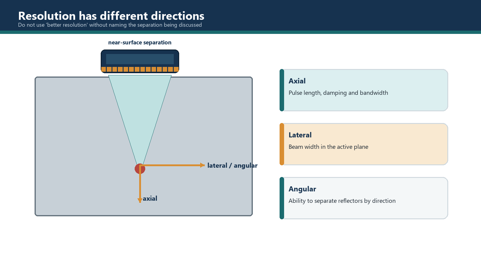
Calling a setup "high resolution" is incomplete. Resolution must identify which reflectors are being separated and in which direction.
Axial resolution separates reflectors along the sound path whose echoes are close in time. It depends mainly on effective pulse length, damping, bandwidth and receiver response; a shorter pulse generally improves separation.
Lateral resolution separates reflectors across the beam at similar path or depth. It follows beam width in the stated plane, influenced by wavelength, aperture, focus, steering and path.
Angular resolution separates responses mainly by direction. It depends on angular beam width, law spacing, aperture, steering and reflector response. A finer displayed angle step may only draw more overlapping laws.
Electronic focusing should therefore not be advertised as an improvement to axial resolution. It mainly changes spatial response across the beam and can improve lateral or angular discrimination and signal-to-noise ratio near the focus. Axial resolution remains principally a pulse and receiver-bandwidth problem.
8.2 Near-surface resolution is not near field
Near-surface resolution concerns the time immediately after transmission. Initial pulse, ring-down, wedge or delay echoes, interface response and receiver recovery can conceal a shallow reflector. Short pulses, suitable bandwidth and delay, stable coupling and controlled reception help reveal it.
Near field is a spatial interference region set by aperture and wavelength. It affects beam shape and focusing, not initial-pulse duration. Changing aperture can change near-field length without shortening the pulse; damping can improve early separation without changing aperture.
Processing may make an early indication easier to see, but it does not guarantee that two physical responses have become resolvable. Filtering, smoothing, averaging or envelope display can suppress noise or alter shape; it can also merge or remove information. Near-surface capability must be demonstrated on representative targets under the intended acquisition settings.
Far-surface resolution has a related practical problem. A reflector close to the back wall can be masked by the back-wall response, beam spread, reverberation or limited time separation. The solution depends on pulse length, angle, path, target orientation, dynamic range and geometry rather than a universal "far-surface" setting.
8.3 Beam width, beam length and the measurement rule
A real beam has no hard edge. Beam width and length are defined by a measurement criterion, commonly a drop relative to the maximum response from a suitable target. The criterion might be -6 dB or another controlled level. A value without the criterion, reflector, scan direction and depth is not reproducible.
In the active plane, beam width is assessed across the electronically controlled aperture direction. In the passive plane, beam behaviour is commonly governed by element elevation, lens, roof and fixed geometry for a one-dimensional array. The two dimensions can differ greatly.
Beam characterisation should state probe, wedge, material, mode, temperature, spectrum, active aperture, angle, focus, reflector, scan direction/increment, amplitude criterion, depth range and relevant processing.
The resulting profile supports technique decisions only within the verified conditions. A beam width measured at one focus and angle is not automatically valid at every depth or law.
8.4 Near field and focal limits
The near-field length increases with aperture size and frequency under comparable conditions and decreases as wavelength increases. Exact relations depend on aperture shape, dimension, medium and the approximation being used.
N = A^2 / (4 lambda) = A^2 f / (4V)
For a rectangular array, active- and passive-plane behaviour should be considered separately. The relation shown is a first-order homogeneous-medium estimate based on the declared aperture and wavelength. In a wedge-coupled refracted setup, part of the path lies in the wedge and projection and refraction alter the effective geometry. Use a relation or model that states the propagation plane, medium, velocity and aperture convention, then verify the resulting beam behaviour on a suitable reference target.
A programmed focus is most effective where the aperture can produce the required curvature with adequate directivity and energy. A requested focal depth beyond the useful focusing range may still produce a focal-law file, but the physical beam can be broad, weak or dominated by other effects. Software acceptance of the number is not beam qualification.
8.5 Focal spot and focal zone
Around a focus, the beam narrows toward a minimum region and then expands. The focal spot is normally described by active- and passive-plane widths at a stated amplitude criterion. The focal zone or depth of field describes a finite region over which the focus remains useful.
For a fixed wavelength and physical aperture, increasing focal distance generally increases focal spot size. For a fixed focus and wavelength, increasing effective aperture generally reduces spot size. For a fixed aperture and focus, a shorter wavelength can reduce the calculated spot, although attenuation and scattering may limit the useful higher-frequency energy.
B_-6dB ~= 1.02 F lambda / A
With unchanged effective aperture and wavelength, increasing focal distance increases the expected focal-spot dimension rather than reducing it.
Stronger focusing usually shortens the useful focal zone and increases sensitivity to depth or position error. A broader focus may be more uniform over depth, so design balances peak discrimination against coverage.
Focal zone = path region satisfying the declared beam-width or amplitude criterion
No single numerical focal-zone relation is universal because the result depends on how the zone boundary is defined. State the amplitude or beam-width criterion, propagation plane, material, aperture, wavelength and valid approximation. Use the method specified by the controlled technique or a validated beam model, and verify the useful zone experimentally.
8.6 Active-plane and passive-plane focusing
A one-dimensional linear array can normally steer and focus electronically in the active plane. In the passive plane, the element elevation is not divided into independently delayed elements, so the beam is controlled by fixed element geometry, lens curvature, roof or acoustic design.
This distinction affects coverage and indication response. A narrow active-plane spot may coexist with a much longer or wider passive-plane beam. A display that appears sharp in the scan plane does not reveal the full three-dimensional insonified volume.
A two-dimensional matrix can control both planes when the required elements or groups are independently addressed. Row-column, multiplexed and grouped designs differ, so focal-law and channel models must match the hardware.
8.7 Fixed focus, multiple focus and DDF
A fixed transmit focus uses one delay pattern for the transmitted pulse. It concentrates the transmitted field around a selected region, subject to the aperture's physical limits.
Multiple groups or focal-law sets can use different transmit focuses to cover separate depth regions. This increases law count, calibration and acquisition burden. It can also change response between groups, so the transition must be verified rather than cosmetically blended.
Dynamic depth focusing changes receive delays as returning echoes arrive from increasing depths. It is dynamic receive focusing, not repeated transmission during one pulse-echo cycle.
DDF does not inherently change transmit excitation, apply depth-dependent gain, reduce file size or increase PRF. An instrument may combine receive focusing with gain, compression or storage choices, but those are implementation decisions and must be described separately.
Worked example 1 - classifying the resolution problem
Scenario A: Two small reflectors lie on nearly the same beam direction at sound paths of 48 mm and 49 mm. Their echoes overlap.
Classification: Primarily axial resolution.
Reasoning: The responses are separated mainly in time along the sound path. Pulse length, damping, bandwidth and receiver response are central; a tighter electronic focus does not directly shorten the pulse.
Scenario B: Two reflectors lie at the same sound path but 3 mm apart across the active scan plane. They appear as one broad response.
Classification: Primarily lateral resolution.
Reasoning: Beam width at that depth is central. Aperture, focus, wavelength and scan sampling must be assessed.
Assumptions: Reflectors have comparable orientation and response, coupling is stable, and acquisition spacing is fine enough not to be the limiting factor.
Worked example 2 - deeper focus and spot size
Given: The same probe, material, mode, frequency and 16-element active aperture are modelled with focal depths of 30 mm and 60 mm.
Assumptions: The same effective aperture and wavelength apply; the approximation used for spot size is valid over both focal depths; attenuation and interface effects are ignored for the relative comparison.
Reasoning: Under the controlled proportional relationship, focal spot size varies directly with focal distance when aperture and wavelength remain fixed. Doubling the focal distance from 30 mm to 60 mm therefore predicts approximately twice the spot dimension in the considered plane.
Conclusion: The deeper focus is not the smaller focus. If a similar spot is required at 60 mm, a larger effective aperture or shorter usable wavelength may be needed, followed by practical verification.
Common traps
- Calling every resolution problem axial. Direction and time separation must be identified.
- Using electronic focus to claim shorter pulses. Focus changes spatial beam formation; it does not directly create axial resolution.
- Treating near-surface resolution as near-field length. One is dominated by early-time pulse/interface behaviour; the other is aperture interference in space.
- Assuming deeper focus means smaller spot. For fixed aperture and frequency, deeper focus generally produces a larger spot.
- Describing a one-dimensional array focus as spherical. Passive-plane behaviour may remain fixed and much broader.
- Quoting beam width without a drop criterion. The number cannot be reproduced without the measurement rule.
- Treating DDF as gain or repeated transmission. It is dynamic receive-delay control.
Chapter summary
Resolution must be defined by direction. Axial resolution separates responses along the sound path and is principally controlled by pulse duration, bandwidth and receiver response. Lateral and angular resolution depend on the spatial beam, aperture, focus, wavelength and sampling. Electronic focusing mainly changes lateral or angular response and SNR around the focus; it does not directly shorten the pulse.
Near-surface resolution is not near-field length. Early response separation depends on ring-down, delay paths, interface echoes and receiver recovery, while near field describes spatial interference close to an aperture. Beam width, focal spot and focal zone require a stated plane, target, depth and amplitude criterion.
For fixed aperture and frequency, a deeper focus generally has a larger focal spot. A one-dimensional linear array focuses electronically in its active plane but does not automatically focus in the passive plane. DDF is dynamic receive focusing and has no inherent promise of higher PRF, lower storage or automatic gain correction.
Study and revision only. This is not an approved inspection procedure, acceptance criterion or qualification.