
CHAPTER 17 · Phased Array Ultrasonics Level 2
Indication Interpretation, Evaluation and Disposition
In this chapter · 13 sections
Purpose
This chapter provides a repeatable route from a recorded response to a controlled result. It separates what the equipment displays from what exists in the component, what the analyst can infer, what a qualified sizing method can measure, and what the governing acceptance source permits. The aim is not to give every coloured feature a dramatic name. It is to preserve evidence, test competing explanations and state conclusions no more strongly than the data support.
Learning outcomes
After completing this chapter, the learner should be able to:
- distinguish indication, discontinuity, relevant response, non-relevant response, false response and defect without assuming one universal vocabulary;
- confirm data validity before interpreting an individual response;
- use position, probe movement, angle, scan direction and multiple views to test an interpretation;
- recognise common geometric, coupling, electronic and processing responses;
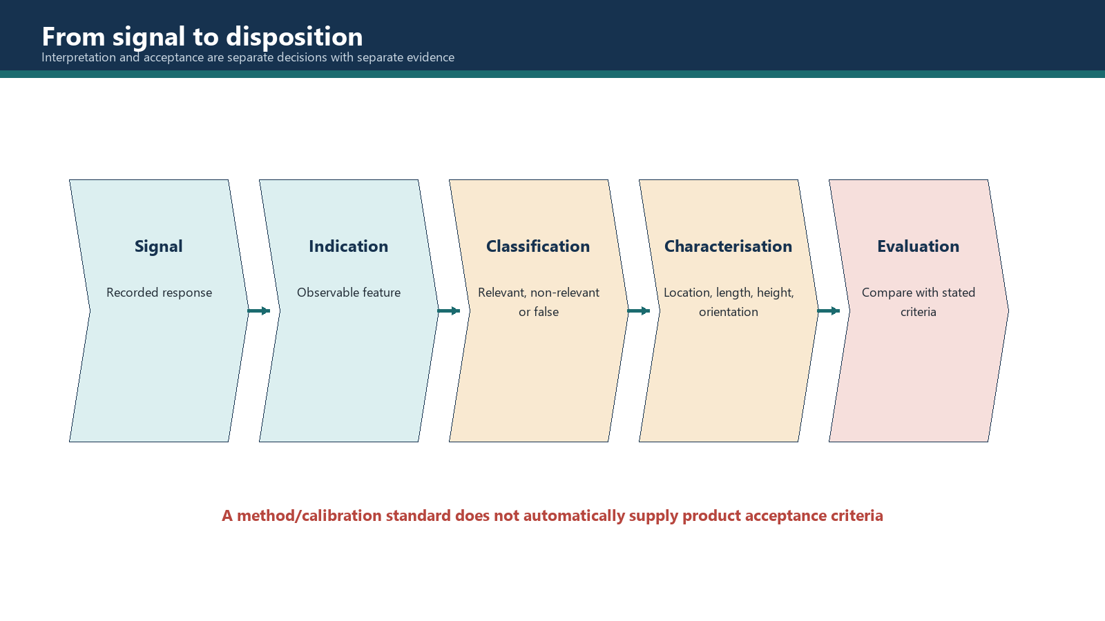
- separate detection, localisation, characterisation, sizing, evaluation and disposition;
- select only sizing methods qualified for the indication and examination conditions;
- apply acceptance criteria from an identified controlled source;
- report uncertainty, limitations and incomplete coverage; and
- recognise when technical or disposition authority must be escalated.
Key terms
Indication; response; discontinuity; imperfection; defect; false indication; non-relevant indication; relevant indication; reportable indication; interpretation; characterisation; localisation; sizing; evaluation; acceptance criteria; disposition; corroboration; echo dynamics; saturation; uncertainty.
17.1 Use terms as controlled decision labels
An indication is observable examination evidence that may require interpretation. It can arise from a material condition, component geometry, coupling, the examination system or processing. A discontinuity is an interruption or variation in material continuity or configuration. Some discontinuities are intentional, benign or permitted.
The words imperfection and defect are not safe universal synonyms. In many systems, defect is reserved for a condition that fails the applicable acceptance criteria; elsewhere a governing document may define it differently. Use the vocabulary and decision thresholds of the controlling document, then state that source in the evaluation record.
Keep the decision stages separate:
- Detection: a response has been observed.
- Localisation: its coordinates and sound path have been established.
- Interpretation: evidence has been used to determine the likely response source.
- Characterisation: likely orientation, morphology and relationship to the component have been assessed.
- Sizing: one or more dimensions have been estimated by a stated method.
- Evaluation: the applicable criteria have been applied to the required measured or classified information.
- Disposition: an authorised status or action has been assigned.
A strong detection may still be poorly sized. A well-located geometric response may be non-relevant. A relevant discontinuity may be acceptable under one controlled criterion and unacceptable under another. None of those distinctions is resolved by changing the colour palette.
Analysis prerequisite — begin with a data-validity gate
Interpretation is unreliable if the examination evidence is not valid. Before analysing a response, confirm:
- the file, component, weld and scan identities;
- the approved technique and setup revision;
- successful calibration and periodic checks covering the acquisition interval;
- required scan coverage and encoded-data continuity;
- correct material, geometry, wedge, law and coordinate inputs;
- suitable coupling and signal-to-noise performance;
- whether stored data are raw, rectified, filtered, compressed or otherwise processed; and
- any field deviation, excluded area, saturation or data loss.
If a check failed or required volume was not scanned, first bound the affected evidence. Do not classify missing or invalid data as “no indication”.
A practical evaluation funnel is:
- preserve the original data and create a controlled analysis copy if processing is needed;
- locate the response in component coordinates and in every available view;
- inspect the contributing A-scans and check for clipping, gate or display artefacts;
- observe response behaviour with aperture position, angle and scan direction;
- compare the location with drawings, surfaces, weld profile and known reflectors;
- test plausible geometric, coupling, electronic and material explanations;
- classify the response using the governing terminology;
- characterise and size it only with supported methods;
- apply the identified acceptance criteria; and
- record the evidence, limitations, reviewer and authorised disposition.
17.2 False, non-relevant and relevant responses
Exact definitions vary among standards and procedures, so the approved document controls the labels. The following working distinctions support analysis without pretending to replace those definitions.
A false indication is apparent evidence produced by something other than the material or geometric condition it appears to represent. Examples can include electrical interference, internal wedge echoes, grating-lobe responses, mode-converted paths, encoder/data alignment errors, coupling loss presented as a map feature, or processing artefacts. Some of these are genuine acoustic responses, but the displayed interpretation is false.
A non-relevant indication arises from a real condition that is not the discontinuity class being evaluated. Normal root or cap geometry, a counterbore, backing, a surface marking, a known interface or an authorised design feature may produce such a response. It must be demonstrated, not dismissed because it occurs at a convenient location.
A relevant indication is associated with a condition that requires evaluation under the governing rules. “Relevant” does not itself mean rejectable. A separate reportability threshold may determine which relevant responses are entered in an indication table, while acceptance criteria determine their final status.
Do not collapse false and non-relevant into one bucket unless the controlling terminology explicitly does so. The corrective action differs: a false response may expose an acquisition or setup problem, while a confirmed geometric response may simply require documented interpretation.
17.3 Geometric and process-related responses
Common geometry sources include weld caps and roots, excess penetration, counterbores, transitions, mismatch, backing, changes in wall thickness, curved surfaces, attachments, cladding interfaces, support contact and reflected or mode-converted beam paths. Their predicted coordinates should be plotted using the actual component geometry. Nominal drawing geometry is a hypothesis until verified.
Process knowledge helps form competing interpretations. A response on a fusion face may be consistent with lack of fusion, but it can also arise from bevel geometry or an adjacent surface. A cluster in cast material may be consistent with porosity or shrinkage, yet coarse structure can create distributed noise. Rolled-product laminations often have a different orientation and movement signature from a weld-plane response. Service cracks may branch, curve or carry oxide and can behave differently from smooth validation notches.
Expected process location is supporting evidence, not proof. An analyst should ask, “What else could produce this response here, and what observation would separate the explanations?”
17.4 Corroborate across views, angles and probe movement
A corrected B-, C- or D-scan is a spatial representation built from setup assumptions. Always inspect the contributing A-scan and, where available, RF information. Verify that the displayed feature is not created by gate boundaries, saturation, interpolation, smoothing, projection or a wrong geometry model.
Useful corroboration can include:
- response rise, peak and fall as the aperture passes the target;
- time or position movement with forward and backward probe travel;
- persistence across adjacent scan lines;
- response over a rational angular band rather than one isolated law;
- behaviour from an opposite direction or complementary skew;
- agreement among sound path, depth, surface projection and known geometry;
- tip-like responses that remain spatially related under movement; and
- comparison with a known geometric feature elsewhere on the component.
These observations are evidence patterns, not universal flaw signatures. A specular planar reflector may appear only over a narrow angular range. A rough or branched condition may respond over many angles. Beam spread can make a small reflector persist across multiple laws. The validated technique and representative experience determine how much weight each observation receives.
When rescanning is allowed, use it to test a stated hypothesis. Record changed position, direction, skew, frequency, aperture or display processing. Do not overwrite the production file or quietly substitute a more persuasive screen capture.
17.5 Characterisation and sizing
Characterisation describes the most defensible understanding of the condition: likely planar or volumetric behaviour, orientation, surface connection, position relative to weld zones, continuity, grouping and confidence. Use qualified language where the evidence is incomplete. “Response consistent with a fusion-face planar condition” is stronger technically than an unsupported declaration of an exact flaw mechanism.
Report the coordinate convention and distinguish:
- scan-axis length from beam-spread length;
- through-wall height from sound-path extent;
- depth below the examination surface from distance along a beam;
- projected surface position from actual reflector position; and
- one connected response from a group requiring interaction rules.
Sizing methods have different assumptions. Amplitude-drop methods depend on beam shape, target orientation, noise, saturation and the specified drop rule. Beam-boundary methods estimate where response crosses a defined portion of the field; they do not trace the physical edge directly. Tip-diffraction or time-of-arrival approaches require identifiable, correctly paired signals and suitable resolution. Length sizing depends on scan increment, beam footprint, encoder performance and the selected endpoint rule.
TCG or DAC provides a reference relationship through path; it does not convert amplitude into real flaw size or remove orientation effects. Never size from a clipped signal. Reduce gain only under the approved analysis method, preserve the original data and record the adjustment. State uncertainty or method resolution where required, especially near surfaces, material interfaces and geometric boundaries.
If the technique was validated for detection but not sizing, report the supported observation and escalate the sizing need. Generating a decimal value does not grant it metrological dignity.
17.6 Apply acceptance criteria and control disposition
Identify the acceptance source by document designation, controlled revision and applicable clause or table. Confirm that it applies to the component, material, joint category, service class, examination stage and technique. A PAUT method standard may govern how the examination is performed without supplying the product's accept/reject rules. A calibration standard does not become an acceptance code merely because both are open on the same desk.
Extract the variables the criteria actually require. These may include amplitude class, length, height, position, surface connection, separation, interaction, component thickness or discontinuity type. Use the values and rounding rules specified by the source. This chapter supplies no universal threshold.
The evaluation record should show:
- the measured and characterised information used;
- the exact acceptance source and revision;
- how grouping or interaction rules were applied;
- limitations or uncertainty affecting the decision;
- the result of the comparison; and
- the identity and authority of the evaluator or reviewer.
Disposition may include conforming, nonconforming, repair, engineering assessment, further examination, unresolved pending information, or incomplete due to access/data quality. The available labels and authorisation route come from the governing system. A Level 2 examiner may perform interpretation and evaluation within authorised scope, but must not amend criteria, waive coverage or approve an engineering concession unless separately empowered to do so.
Worked field scenarios
Scenario 1 — Root response or root condition?
An encoded weld scan shows a continuous response near the root. It tracks the root line, appears over several adjacent apertures and changes position as expected when the probe moves. Drawing review identifies possible internal mismatch, but the as-built profile is unavailable. A second-direction scan produces a different response pattern and one local segment extends beyond the predicted geometric line.
The analyst does not label the whole feature “root geometry” or “lack of penetration”. The continuous portion is recorded as a likely geometric response with the basis and confidence stated. The local extension remains relevant, is characterised and sized using the authorised method, then evaluated against the identified product criteria. If the geometry cannot be confirmed, the result is escalated or additional examination is requested.
Scenario 2 — A coloured patch caused by coupling loss
A C-scan contains a low-amplitude patch beside a high-amplitude edge. The raw A-scans show simultaneous back-wall loss, elevated interface noise and intermittent data drop-out. The patch aligns with a rough surface band rather than a credible discontinuity plane.
The response is evidence of invalid or degraded acquisition, not proof that the material is clear and not automatically a false “flaw”. The affected zone is bounded, surface and coupling conditions are corrected, required calibration checks are confirmed, and the zone is reacquired under the controlled technique. Both the original and replacement data remain traceable.
Common traps
- Treating every indication as a discontinuity.
- Calling every relevant response a defect before applying criteria.
- Labelling an awkward signal “geometry” without corroboration.
- Classifying an unscanned or invalid area as acceptable.
- Trusting a corrected view without inspecting contributing A-scans.
- Using expected fabrication flaws as proof of response identity.
- Measuring a saturated echo.
- Reporting sound path as through-wall depth.
- Treating TCG-corrected amplitude as physical flaw size.
- Applying criteria from the examination-method document without confirming authority.
- Changing acceptance rules to accommodate an uncertain result.
Chapter summary
Evaluation begins with valid, traceable data. Responses are located and tested against acoustic, geometric, process and system explanations before relevance is assigned. Characterisation and sizing use only supported observations and qualified methods. Acceptance is a controlled comparison with an identified source; disposition requires the designated authority. The final conclusion must preserve uncertainty and limitations instead of converting them into false precision.
Study and revision only. This is not an approved inspection procedure, acceptance criterion or qualification.