
CHAPTER 7 · FMC / TFM / PCI Level 2
Propagation Modes, Views and Acoustic Paths
In this chapter · 15 sections
Purpose
FMC contains many transmitter–receiver waveforms, but it does not label which echo travelled by which route. The reconstruction assigns a route. That choice determines the travel time, the image location and the reflector orientations to which the view may respond. Multi-view TFM can be powerful because the same dataset can be examined through direct, reflected and mode-converted paths. It can also produce an impressive gallery of wrong answers if the paths are chosen from a software menu without geometry and coverage checks.
This chapter makes view selection intentional. Every selected view must have a declared notation, a complete ray/path diagram, a physical access argument and a verification target. A short list of justified views is more useful than twenty unexplained images.
Learning outcomes
After completing this chapter, the learner will be able to:
document transmit and receive paths without relying on vendor shorthand;
distinguish direct, reflected, tandem-like and mode-converted path families;
identify the component surfaces used by each path;
select complementary views for likely reflector orientations and diffracting tips;
reject impossible or poorly supported paths; and
explain why one reflector can appear differently across valid views.
Crossover map: from scan angle to path family
| Familiar UT/PAUT planning decision | Multi-view TFM decision |
|---|---|
| Select an angle and probe position to insonify a target. | Select a transmit path and receive path whose combined geometry can interact with the target. |
| Use first-leg or second-leg sound and mark skip distance. | Declare every direct or reflected leg and the surface participating in each reflection. |
| Expect planar reflectors to be directionally sensitive. | Choose complementary views because specular, corner and tip responses couple into different path families. |
| Check mode conversion and geometry echoes. | Model conversions and boundaries deliberately, while also testing whether unselected conversions create artifacts. |
| Draw a PAUT scan plan showing coverage. | Draw each TFM view with element aperture, interfaces, ROI, modes and shadow zones. |
| Verify a beam on representative targets. | Verify each reported path/view on targets that challenge its position and orientation sensitivity. |
A neutral path notation
The manual uses a path label in which a hyphen separates the transmit side from the receive side. Letters identify the sequence of specimen bulk-wave legs:
L means longitudinal wave;
T means transverse, or shear, wave;
the letters before the hyphen describe the transmitter-to-pixel side;
the letters after the hyphen describe the pixel-to-receiver side; and
repeated letters show multiple legs separated by a declared reflection.
Examples include:
L-L: direct longitudinal transmit and direct longitudinal receive;
T-T: direct transverse transmit and direct transverse receive;
TT-T: a two-leg transverse transmit route using the declared reflection, with a direct transverse receive route;
T-TT: the reciprocal ordering of that route;
LL-L: a two-leg longitudinal transmit route and direct longitudinal receive; and
LT-T: a two-leg transmit route involving a declared longitudinal-to-transverse conversion, followed by direct transverse reception.
The label alone is incomplete. TT-T does not state which surface causes the reflection, where the probe is located, whether the pixel lies before or after the reflection, or whether the transmitter and receiver apertures are the same. Every technique must pair the label with a diagram and written definition.
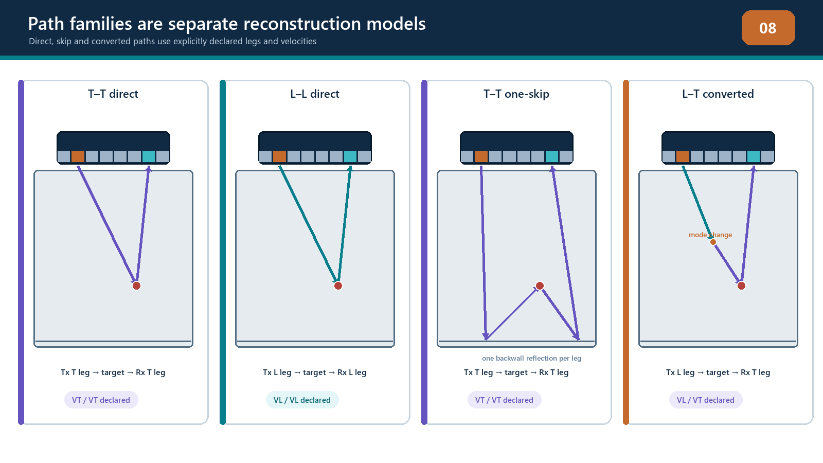
Commercial systems may use terms such as wave set, 2T, 3T, 4T, self-tandem, intermode or a branded combined-image name. These can be useful interface labels, but they are not assumed to be universal. The implementation profile must translate them into the explicit transmit and receive routes used by that software version.
Direct paths
Direct paths travel from the transmitting element to the candidate pixel and from the pixel to the receiving element without an internal boundary reflection. Direct L-L is common for normal or near-normal longitudinal imaging. Direct T-T is common where wedge refraction creates shear-wave access to the ROI.
Direct does not mean simple in every setup. A wedge path still includes the wedge-to-component interface. A curved surface may require a different entry point for each element and pixel. Longitudinal-to-shear conversion at the entry interface may be part of establishing a direct specimen T path even though the path label normally describes specimen legs.
Direct views often provide strong responses from small volumetric targets and surfaces oriented to return energy to the array. They may have poor access to near-vertical planar reflectors because a specular reflection travels away from the receive aperture. Tip diffraction can remain visible even when the face response is weak, but it must be above noise and supported across an effective aperture.
Reflected and skip paths
A reflected path deliberately uses a known component boundary, often the backwall. In conventional angle-beam UT, first-leg and second-leg reasoning already teaches the geometry. Multi-view TFM extends that reasoning by allowing transmit and receive sides to use different numbers of legs.
For TT-T, the transmit route may travel from the array to the backwall, reflect, then reach the pixel, while the receive route returns directly from the pixel to the array. T-TT reverses those roles. A TT-TT view uses a reflected route on both sides. Depending on component geometry, such paths can create tandem-like access to a vertical reflector or its tips.
Each boundary reflection adds conditions:
the surface position and orientation must be known;
the incident and reflected route must fit inside the component;
the reflection point must lie on a usable surface;
attenuation and path length increase;
roughness, curvature, cladding or corrosion may scatter or distort energy; and
other geometry echoes may share similar times.
Terms such as half-skip and full-skip can be ambiguous when applied to separate transmit and receive sides. Use them only after defining the convention. The explicit leg diagram remains the authority.
Mode-converted paths
At an interface or reflector, incident energy can produce more than one wave mode. A selected reconstruction can model a conversion, for example a longitudinal leg followed by a transverse leg. Such a view may access an orientation that a same-mode path misses.
Mode conversion is not free extra coverage. The conversion coefficient depends on angle, materials, interface condition and polarization. A time-of-flight route can be mathematically valid while its transmitted amplitude is negligible. The chosen modes must also use the correct velocities on their respective legs. Substituting one average velocity may place the image incorrectly and destroy phase alignment.
Unmodelled conversions can create artifacts. If an L-T event is reconstructed under an L-L assumption, some pixels may still collect partial alignment and form a misplaced feature. When a response cannot be explained by the selected path, calculate plausible alternative paths before calling it a defect.
Reciprocity and view ordering
In a linear reciprocal acoustic system, exchanging transmitter and receiver can produce similar elementary responses. This is useful when comparing TT-T and T-TT. It does not guarantee identical displayed views. Differences can arise from:
unequal transmitter and receiver electronics;
different sub-apertures or weights;
channel exclusions;
acquisition sequence or coupling change;
direction-dependent transmission at interfaces;
interpolation and processing; and
a reduced matrix that does not contain both ordered pairs.
Use reciprocity as a diagnostic expectation. Do not use it to silently invent missing data or rename a reduced acquisition as full FMC.
Reflector behaviour across views
The response is a product of the path and the scatterer. A small spherical or cylindrical reflector may redirect energy across many angles, although a side-drilled hole is not a perfect point. A smooth planar reflector tends to return a strong specular response only for favourable incident and receive directions. A crack tip can diffract weak energy over a wider angular range. A corner between a planar flaw and a surface can produce a strong corner-trap response for selected routes.
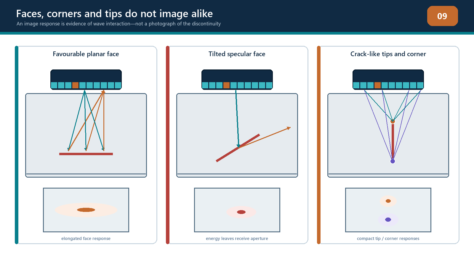
This leads to a practical view strategy:
use a direct view for general volumetric and favourably oriented responses;
add a reflected or tandem-like view when vertical or steep planar reflectors are credible targets;
use complementary views to seek upper and lower tip evidence;
include a view that reveals relevant geometry boundaries and expected benign responses; and
retain conventional PAUT, amplitude TFM or another method when it supplies evidence that a phase or special path suppresses.
Different valid views can place the response at the same physical coordinate but show different shape and intensity. If two views place a feature at different coordinates, investigate path assumptions, surface geometry, velocity and whether one image is a mirrored or ghost solution.
Coverage, directivity and shadow zones
A ray line on a scan plan establishes geometry, not sensitivity. Real array elements have finite directivity. At high departure angles, an element may transmit or receive poorly. Wedge transmission losses, aperture size, path length and material attenuation further change sensitivity. A planar target may direct its return outside the array even when the ray intersects it.
A coverage or acoustic-influence map can help identify:
which elements contribute to each part of the ROI;
regions near directivity limits;
path reflection points;
unilluminated corners;
regions shadowed by geometry; and
transitions where one view should hand over to another.
Such a model is a planning tool. It depends on its material, probe and reflector assumptions. Prove coverage with representative targets distributed through the examination volume and at challenging orientations.
Geometry responses and path degeneracy
Backwalls, sidewalls, counterbores, weld caps, roots, cladding interfaces and probe/wedge echoes are legitimate acoustic reflectors. A TFM algorithm does not know whether a coherent event is a defect. If its time matches the selected path to a candidate pixel, it can be displayed.
Path degeneracy occurs when different physical routes have equal or similar travel times. A boundary echo under one mode can resemble a target echo under another. Common safeguards are:
predict geometry signatures before scanning;
reconstruct known-good reference data;
compare response movement as the probe advances;
inspect elementary A-scans and aperture support;
compare complementary views;
challenge the response with an alternative path model; and
confirm that its coordinate follows the component rather than a fixed instrument delay.
More views can expose a false interpretation, but indiscriminately adding views also creates more opportunities for coincidental alignment. View count is not evidence quality.
Field workflow: selecting a justified view set
Define the component, coordinate system, accessible surfaces and target flaw types.
Mark material regions, known boundaries, thickness changes and uncertain geometry.
Draw the simplest direct L and T paths that can reach the target volume.
Add reflected or converted paths only to address a specific coverage or orientation gap.
Name each view using the declared notation and draw transmit and receive sides separately.
Check wedge/interface crossings, reflection points and mode velocities.
Assess element directivity, aperture support, path length and expected scattering direction.
Predict benign geometry responses and shadow zones.
Select representative reference targets for each view.
Reject views that are impossible, redundant, unsupported or outside the procedure.
Freeze the limited view set and its essential variables.
Escalate if coverage requires an undocumented proprietary mode or unverified material model.
Practical 7 — Create and challenge a mode-view plan
Aim
Prepare a defensible view plan for a butt weld or representative plate component, then identify and reject attractive but invalid paths.
Resources
a controlled component drawing with thickness, weld profile and scan surfaces;
a declared probe and wedge model;
longitudinal and transverse velocities approved for the exercise;
target set including a small volumetric reflector, a steep planar reflector and upper/lower crack-tip positions;
ray-sketching paper or modelling software; and
known-good reference data for selected views.
Method
Establish the component coordinate system and mark the complete examination volume.
Draw direct L-L and T-T candidates from the available scan surface.
Draw at least two reflected candidates using the backwall and one mode-converted candidate.
For every candidate, label each specimen leg, reflection surface, conversion and transmit/receive ordering.
Calculate approximate path lengths and travel times to one target coordinate.
Mark reflection points and check that they lie on real, accessible portions of the boundary.
Sketch the likely specular return direction for the planar target and the broader diffraction from its tips.
Rate each view for geometry validity, expected aperture support, target relevance and artifact risk.
Select no more than four justified views. State the unique purpose of each.
Reject at least two candidates in writing. One must fail geometry and one must fail sensitivity or relevance.
Compare predictions with the reference dataset. Identify expected backwall, root or sidewall responses before examining target indications.
Revise the plan only when the evidence identifies a declared assumption that was wrong.
Evidence to retain
scaled or dimensioned path diagrams;
view-name dictionary;
calculation sheet for the common target coordinate;
view-selection table with reasons;
two documented rejected paths;
predicted geometry-response map;
matched reconstruction screenshots; and
instructor witness of the final coverage argument.
Stop rules
Stop if a surface position or material velocity is unknown; a reflection point falls outside the component; the selected conversion is not supported by the implementation; the view depends on a branded label that cannot be translated into an explicit path; the target lies outside usable directivity or qualified ROI; or the reference target is not detected with the required evidence. Do not retain a view merely because it produces an attractive indication.
Common traps
Treating software mode names as universal path definitions.
Omitting the reflection surface or conversion point from the diagram.
Assuming a mathematically short path has useful acoustic sensitivity.
Calling every indirect path “second leg” without separating transmit and receive sides.
Believing reciprocal orderings must display identically.
Selecting many views without assigning each a unique purpose.
Using a side-drilled hole alone to prove sensitivity to steep planar flaws.
Forgetting element directivity at extreme path angles.
Interpreting a coherent backwall or root response as a defect.
Adjusting component thickness until a geometry artifact disappears.
Chapter summary
A TFM view is defined by a transmitter-to-pixel path and a pixel-to-receiver path. The book’s neutral notation separates those sides with a hyphen and uses L and T to list specimen wave-mode legs. Labels must always be accompanied by a complete path diagram because shorthand does not identify surfaces, reflection points, conversions, apertures or implementation details.
Direct, reflected and converted paths provide complementary access to reflector orientations, but every additional leg increases model and sensitivity demands. A valid travel-time solution does not guarantee adequate energy. View selection must consider element directivity, boundary condition, attenuation, target scattering and representative verification. The right outcome is a small, justified view set whose geometry responses and limitations are understood.
Study and revision only. This is not an approved inspection procedure, acceptance criterion or qualification.