
CHAPTER 16 · Phased Array Ultrasonics Level 2
Developing and Validating an Inspection Technique
In this chapter · 14 sections
Purpose
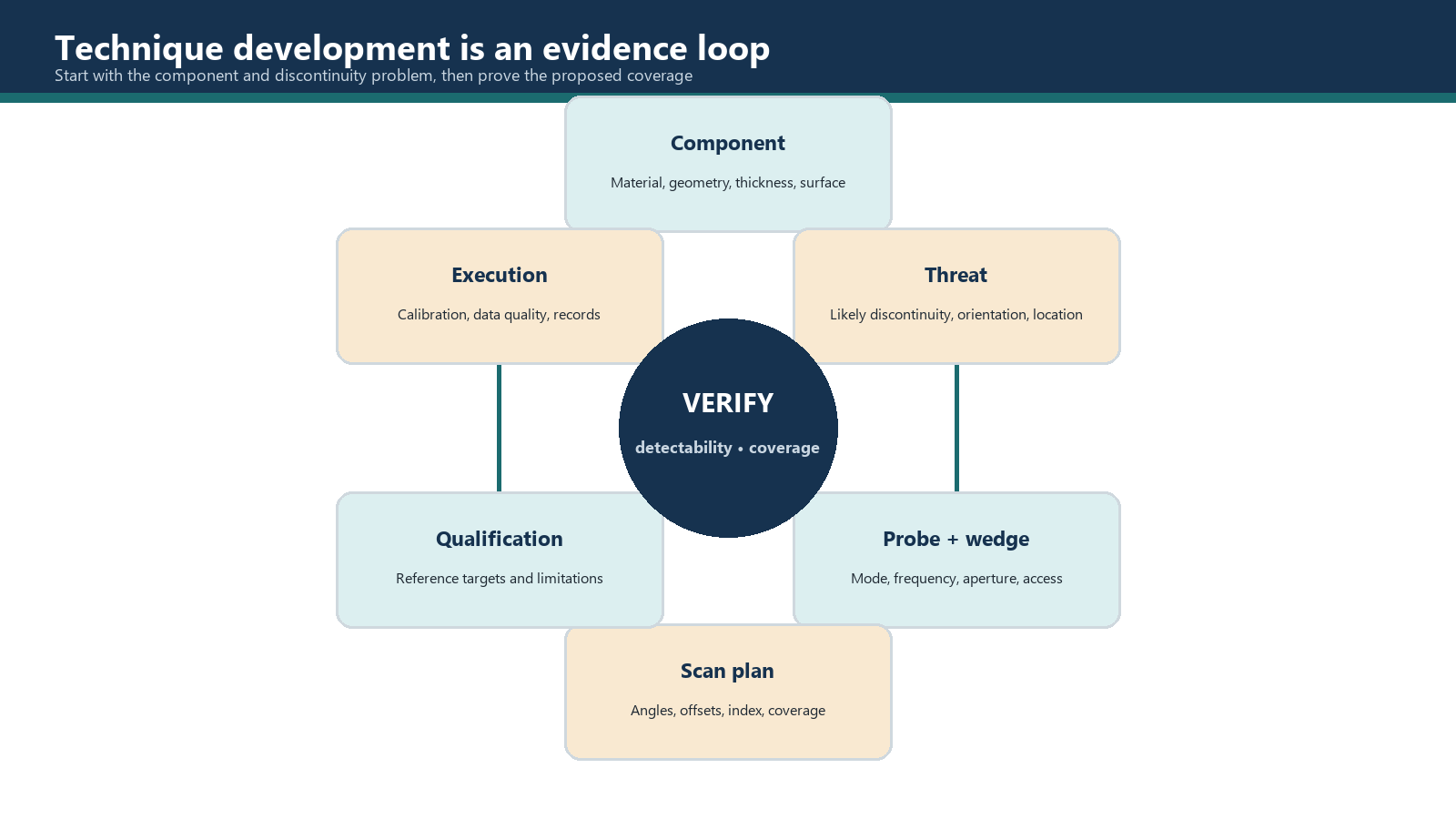
This chapter turns component information and examination requirements into a PAUT technique that can be performed, checked and defended. Technique development is not a hunt for an attractive sector scan. It is a controlled design task: identify what must be found, understand how the component may affect sound, select a suitable probe and scanning arrangement, demonstrate coverage and response, document limitations, and obtain the required authorisation before production use.
The chapter deals with technical decision-making rather than instrument menus. A saved setup is one output of the process, not the process itself.
Learning outcomes
After completing this chapter, the learner should be able to:
- translate the examination scope and governing requirements into technique inputs;
- relate manufacturing route, material condition and service history to credible discontinuity locations and orientations;
- select frequency and bandwidth by balancing propagation, resolution and data quality;
- select an array, aperture and wedge for the required beam directions and access;
- assess surface condition, curvature, coupling and scanner clearance before finalising a scan plan;
- distinguish calculated coverage from demonstrated examination capability;
- prepare evidence for technique validation without claiming an unsupported probability of detection;
- recognise changes that require review, revalidation or new authorisation; and
- state the boundaries among a method, procedure, written instruction, validation record, acceptance criteria and examination report.
Key terms
Technique development; design input; examination volume; target discontinuity; array; active aperture; frequency; bandwidth; steering; focusing; wedge; delay line; coupling; scan plan; coverage; essential variable; validation; demonstration; qualification; limitation; deviation; authorisation.
16.1 Start with the component, material and credible discontinuities
Technique development converts a defined inspection problem into an executable set of controls. The order matters because later choices depend on earlier facts.
A practical development sequence is:
- identify the component, examination volume, access and condition;
- identify the contractual and controlled technical requirements;
- establish the material, product form, joining process and service history;
- list credible discontinuity types, positions and orientations;
- define the information the examination must provide—detection, location, characterisation, sizing or a combination;
- select candidate wave modes, frequencies, arrays, apertures, wedges and scan directions;
- model the beam paths and mechanical coverage;
- test the proposed arrangement on suitable known features or a representative validation specimen;
- record capability, constraints and unresolved areas;
- issue the written technique controls and obtain the required approval; and
- monitor field performance and route changes through document control.
The method is the broad technical approach. A procedure controls its application across a stated scope, while a job-specific written instruction defines field actions. Validation supplies capability evidence; authorisation grants formal permission. Acceptance criteria govern later conformity decisions, and the report records the work and result. These functions remain separate even when one document references several of them.
Component and discontinuity design inputs
Define the examination object
The developer needs controlled dimensions, material designation, product form, heat treatment where relevant, surface condition, weld details, repair history, operating condition, and accessible scanning surfaces. Drawings should be checked against the actual component. A nominal wall thickness is not enough if reinforcement, counterbores, tapers, curvature, attachments or local wall loss alter the beam path.
Establish a component coordinate system before designing coverage. State the origin, positive scan and index directions, reference surfaces, clock convention for cylindrical components, and any datum used to locate indications. This prevents the elegant but useless result that is accurately plotted in the wrong coordinate system.
Build a discontinuity hypothesis
A discontinuity hypothesis is a reasoned list of conditions that may exist, where they may occur and how they are likely to be oriented. It is not a prediction that every component contains those conditions. It guides beam direction, scan access and validation targets.
For each credible condition, record:
- the initiating process or service mechanism;
- likely zone and depth range;
- likely plane, major axis and surface connection;
- whether the response is expected to be specular, diffuse, tip-diffracted or mixed;
- which beam directions could interact effectively;
- what geometric features could produce competing responses; and
- whether detection alone is sufficient or a qualified sizing method is required.
The target list must come from applicable engineering information, fabrication knowledge, service history and controlled requirements. A generic weld-flaw poster is not a substitute for knowing how the item was made.
16.2 Select frequency and bandwidth for the material and task
Frequency selection balances competing effects. A higher frequency produces a shorter wavelength in the same material and can support improved resolution, but it is generally more vulnerable to attenuation and scattering. A lower frequency may improve penetration and signal stability while reducing the ability to separate closely spaced responses. Grain size, anisotropy, path length, surface condition, required resolution and expected target response all matter.
Bandwidth describes the useful frequency range of the complete pulse-echo chain under defined measurement conditions. A broader useful band can support a shorter pulse and improved axial separation; it can also change noise and sensitivity. Nominal centre frequency alone does not describe pulse length or field performance. Probe damping, wedge path, filters, digitising settings and the component all influence the received spectrum.
Candidate selections should be compared using representative paths and settings. Record signal-to-noise behaviour, pulse separation, reference-target response and any material noise that could obscure the examination volume. Do not choose a probe solely because a catalogue frequency worked on a different grade, thickness or heat treatment.
16.3 Select the array and active aperture
Array selection begins with the planes in which the beam must be controlled. A linear array provides electronic control primarily in its active plane. Matrix or other multi-dimensional arrangements may support steering or focusing in a second plane, but their channel, data and validation demands differ. Curved or specialised arrays may improve contact or coverage for a defined geometry.
The active aperture is formed by selected elements and pitch; count alone is not width. Aperture affects spread, near-field structure, focus, sensitivity, footprint and electronic-stepping room. A larger aperture can lengthen the near field, increase contact sensitivity, restrict steering or prevent the required scan position.
Consider pitch relative to wavelength and steering range because unsuitable combinations can produce grating lobes. Review lobe response at the actual laws and paths. Programmed steering beyond the physical interface or array capability does not create a valid beam; angle labels above ninety degrees require their convention and geometry to be resolved.
Focusing should be applied only where it benefits the defined region. An electronic focus has finite extent and its quality changes away from the design point. Deeper focus does not guarantee a smaller spot; aperture, frequency, steering, path and material determine the result. Near-surface resolution, acoustic near-field behaviour and focal location are related design issues but are not interchangeable terms.
16.4 Select the wedge or delay arrangement
The wedge must fit the probe, component and beam paths. Inputs include contact geometry, incident angle, condition-specific velocity, roof angle, element reference position, wear, attenuation, mode conversion, footprint, irrigation, temperature capability and mounting.
A delay line or water path can separate interface and component responses, protect the probe or move an unwanted repetition. Added delay can move interference into another important region, so plot interface, back-wall and repeated paths across the display range.
For curved components, assess whether the wedge is contoured, flexibly coupled or sufficiently narrow to maintain stable contact. A flat wedge rocking on a small diameter can change entry conditions and amplitude while the software continues to draw a beautifully confident beam. Physical fit wins that argument.
The selected wedge data are focal-law inputs. Wedge-delay calibration later corrects time/path offsets for the assembled setup; it cannot repair incorrect wedge angle, height, velocity, element position or component geometry. Temperature-dependent changes must be managed through the applicable procedure and validation basis.
16.5 Surface, access and coupling are design inputs
Inspect the proposed scanning surface before approving the technique. Record roughness, coatings, scale, weld spatter, curvature, waviness, temperature, contamination and obstacles. Surface preparation must be authorised and must not harm the component. More couplant may stabilise some rough surfaces, but it does not restore a beam distorted by severe gaps or geometry.
Confirm the complete scanner footprint and travel, including cable bend radius, encoder contact, probe index offsets, water or couplant delivery, start and stop allowance, and clearance at attachments. Consider how an operator will maintain orientation and pressure. One-sided access, a restricted raster or an unscannable band is a coverage constraint, not an administrative note to be added after scanning.
Couplant choice and delivery should suit material compatibility, temperature, surface orientation and examination duration. Validation should represent the intended coupling condition. If field coupling behaves differently from the validated condition, the response must be assessed under the change-control rules.
16.6 Build and demonstrate the scan plan
Purpose
The scan plan connects the acoustic design to physical probe positions and demonstrates how the required volume will be interrogated.
Prerequisites
Use controlled component geometry, identified scan surfaces, candidate probe/wedge data, a defined law set, target-discontinuity orientations, coordinate conventions, required overlap, and the governing coverage requirements.
Method
- Draw the component cross-section and relevant three-dimensional features to scale.
- Define the examination volume and any adjacent parent material required by the scope.
- Plot probe positions, index offsets, scan directions, beam modes and intended sound paths.
- Include skipped paths, reflections and interfaces that can create useful or competing responses.
- Map the effective beam region for the laws used; a centreline alone is not coverage.
- Check near-surface and far-surface zones, fusion faces, root, cap, transitions and geometric shadowing.
- Define scan increment, speed, encoder axes and acquisition conditions consistent with the smallest feature the approved technique is intended to resolve.
- Identify coverage obtained from each direction and any required complementary scan.
- Mark inaccessible, weakly demonstrated or excluded volumes explicitly.
- Verify the model on known features or a suitable specimen using the complete field configuration.
Acceptance evidence
Evidence should include the controlled scan-plan drawing, setup identity, beam-model assumptions, demonstrated target responses, encoded position checks, data-quality observations and a coverage statement tied to the examination scope. Validation of artificial targets demonstrates response to those targets under the trial conditions. It does not, by itself, establish a minimum detectable real flaw or a probability of detection.
Failure modes
Common failures include plotting only nominal beam centre lines, ignoring the probe footprint, assuming equal performance at every angle, using a validation target with an unrepresentative orientation, omitting geometric shadow zones, relying on an unverified software material model, or claiming full coverage when only geometric intersection has been shown.
Records
Retain drawing revision, model inputs, law file, probe and wedge identities, specimen and target details, trial data, observed limitations, review comments, approval status and links to the resulting procedure or written instruction.
16.7 Product, joining-process and service cases
Cast products. Castings can be examined ultrasonically, although grain structure, scattering, complex surfaces and shrinkage, porosity, inclusions or hot tears can make the task difficult. Capability depends on alloy, section, process and target. Trials may favour lower frequency, shorter paths, multiple directions or another method. Any unresolved limitation requires authorised engineering action.
Forgings and extrusions. Working can elongate inclusions and align structure with material flow. Laps, bursts, segregation and remnants of primary-process discontinuities may have preferred orientations. Technique design should consider the actual forging or extrusion flow and machining allowance, not merely the finished external shape.
Rolled plate. Plate is a wrought product made by rolling; it is not a type of forging. Laminations and elongated inclusions commonly lie broadly parallel to the rolled surfaces, while edge, forming and service conditions can introduce other orientations. Normal-beam and angle-beam arrangements answer different questions and may both be needed where the scope includes parent plate and joints.
Fusion welds. Joint preparation, process, sequence and repairs influence credible conditions. Lack of fusion can follow fusion faces or inter-run boundaries; penetration problems occur near the root; cracks may occur inside or beyond the weld. Flux-derived slag is not characteristic of gas tungsten or gas metal arc welding, but oxide, silicate, tungsten and other inclusions can occur. Design must follow the actual process.
Friction-stir welds. This solid-state process plasticises and transports material below bulk melting. Possible conditions include root flaws, voids, tunnel-type features, hooking and weakly bonded interfaces. Validation determines whether multiple beam planes or more capable array geometry are needed.
Service damage. Fatigue cracking, stress-corrosion cracking, creep damage, hydrogen-related damage, erosion and corrosion have different distributions and acoustic behaviours. Review stress direction, temperature, medium, load cycles, previous repairs and known damage sites. A technique designed for fabrication lack of fusion may be poorly suited to a branched service crack even when both are described casually as “planar”.
16.8 Validation, authorisation and change control
Validation asks whether the technique is capable of its defined task. Its form depends on the governing requirements and risk. It may combine calculations, modelling, block trials, representative mock-ups, blind demonstrations, prior qualified evidence and engineering review. The evidence must match the claim. A successful open trial on known reflectors supports setup and coverage evidence; it is not a blind probability-of-detection study.
Define validation variables before the trial. These may include component geometry and material range, probe/wedge family, frequency, aperture, wave mode, law range, focus, scan direction, calibration method, coupling, encoded sampling, analysis process and sizing method. The authorised document should state which changes are permitted without further review and which are essential enough to require partial or full revalidation.
Field deviations are not repaired retrospectively by editing the setup name. Stop, preserve the data, record the difference, obtain the specified technical review, repeat affected calibration or validation, and determine whether earlier data remain usable. Approval must come from the role designated by the quality system, contract and certification scheme; this manual does not invent a universal personnel authority.
Worked field scenarios
Scenario 1 — Restricted access at a narrow-groove weld
A pipe weld can be scanned from one side, but an attachment prevents a complete second-side pass. The fabrication record identifies a narrow groove made by a gas-shielded fusion process. The developer lists fusion-face and root conditions as primary targets and plots beams intended to intersect their likely planes. Trials show good response from the accessible fusion face but a poorly demonstrated shadowed root sector.
The correct outcome is not to increase gain and declare coverage. The technique record separates the demonstrated volume from the unresolved volume. Options are assessed: a smaller-footprint wedge, an additional skewed or opposite-direction arrangement, temporary attachment removal if authorised, a complementary method, or formal acceptance of a limited scope by the responsible engineering authority. The report must later carry the approved limitation if it remains.
Scenario 2 — Noisy response in a cast pump body
A proposed high-frequency setup produces dense material noise before the longest required path. Rather than concluding that castings cannot be examined, the developer compares candidate lower-frequency and narrower-band arrangements, alternative surfaces and shorter paths on a representative section. One arrangement improves coherent target response but cannot demonstrate the smallest target in a thick transition.
The validation record states where the method is supported and where it is not. Engineering then decides whether to change the examination requirement, use another method, redesign access or reject the technique for that zone. The limitation is a technical result, not an operator failure.
Common traps
- Selecting a probe before defining credible discontinuity orientations.
- Treating nominal frequency as a complete description of resolution.
- Calling element count the aperture width without considering pitch.
- Assuming a deeper electronic focus always creates a smaller focal spot.
- Accepting a simulated beam that cannot be coupled or positioned in the field.
- Using gain to compensate for poor contact, scattering or missing coverage.
- Treating a scan-plan centreline as proof of complete volume coverage.
- Describing rolled plate as forged product.
- Treating friction-stir welding as a melting process.
- Claiming probability of detection from a visible artificial-reflector response.
- Allowing an unapproved field change to become the new technique by repetition.
Chapter summary
A defensible PAUT technique begins with controlled requirements, component facts and a reasoned discontinuity hypothesis. Frequency, bandwidth, array, aperture, wedge, surface, coupling and scan access are selected as one interacting system. Coverage is modelled, then challenged with suitable evidence. Validation supports only the capability actually demonstrated, while authorisation controls its release and any later change. Acceptance criteria and reporting remain separate downstream activities.
Study and revision only. This is not an approved inspection procedure, acceptance criterion or qualification.