
CHAPTER 42 · Phased Array Ultrasonics Level 3
Qualifying a PAUT Technique Through Evidence
In this chapter · 25 sections
Why this matters
A technique finds every machined notch in one demonstration block. That is encouraging, but it does not yet prove reliable detection throughout a production weld family. The result may belong only to that setup, those targets and those conditions. PAUT qualification is the disciplined process of defining what the inspection must achieve, challenging it under relevant variation and limiting the claim to what the evidence supports. This chapter follows one ferritic weld technique from its first performance claim through modelling, representative specimens, robustness work, blind confirmation, transfer and independent review. The mathematics appears only after the physical decisions are clear.
What you already need
- Competent PAUT Level 2 setup, calibration, scanning and interpretation.
- The difference between coverage, sensitivity, detection, location and sizing.
- The calibration-state and uncertainty foundations from Chapter 41.
- Basic understanding of focal laws, acquisition completeness and weld geometry.
- The ability to read a simple results table and percentage.
What you will learn
- Write a bounded and testable PAUT performance claim.
- Connect each claim and essential variable to suitable evidence.
- Separate model verification, model validation and experimental demonstration.
- Design representative, robust and blind qualification work.
- Interpret hit fraction, misses and false calls without overstating POD.
- Decide what must be repeated after transfer or technical change.
Words you will meet
- Qualification: evidence that a defined inspection system meets a defined claim.
- Performance claim: bounded statement of the output an inspection must achieve.
- Essential variable: factor whose change can materially affect the claim.
- Verification: checking that a model or calculation is solved as intended.
- Validation: checking that the model represents relevant physical behaviour.
- Robustness: ability to maintain performance under plausible variation.
- Blind trial: demonstration in which target truth is withheld from decision-makers.
- POD: probability of detection for a defined system and target population.
- False call: non-target response incorrectly declared relevant.
- Transfer: controlled movement of a qualified technique to another system or setting.
42.1 Start with the production decision, not the demonstration block
Consider a proposed encoded PAUT examination of ferritic single-V welds from 20 mm to 40 mm thick. The production need is to detect and locate planar fusion flaws in the weld and heat-affected zone from one accessible surface. The team also wants to report through-wall height where two boundaries can be resolved.
These are not one claim. Detection asks whether a relevant target is found. Location asks whether its reported coordinate is sufficiently accurate. Height sizing asks whether two physical boundaries are identified and separated. False-call control asks whether geometry and noise are kept from becoming unnecessary repairs. One impressive image cannot prove all four.
The first controlled statement can declare that the defined PAUT system will detect and locate the stated planar-target population inside the defined weld volume. It applies only with qualified personnel and across the evidenced thickness, surface and essential-variable ranges. Height sizing is claimed only where the qualified boundary method resolves both tips. The statement can be tested because it names the system, population, volume, outputs and limits.
The inspection system is broader than the instrument. It includes equipment, probe, wedge, scanner, focal laws, software, component population, environment, calibration, operators, analysts and decision rule. Reliability belongs to that complete system and population, not to “PAUT” as a method name. POD guidance makes this boundary central. [R033] [R034]
If the production decision changes, the evidence need changes. A technique used only to screen for large lack of fusion needs different evidence from one supplying crack height to an integrity assessment. The performance claim should be agreed before targets are chosen, because easy targets have an awkward habit of making almost any technique look heroic.
42.2 Turn the claim into outputs that can be compared with truth
Each claimed output needs an observable result, reference truth and comparison rule. For the continuing weld case, detection may mean a reportable response produced by the released analysis rule inside the applicable volume. Location may mean the difference between reported and reference x- and z-coordinates. Height may mean the difference between two reported tip coordinates compared with established target height.
Coverage also needs a definition. A ray crossing the weld is geometric coverage. A field model above a stated pressure or response threshold is field-based coverage. A target response in a specimen is demonstrated response. These forms answer different parts of the problem and should not be renamed as one another.
The decision rule is part of the output. Suppose development analysts use multi-angle convergence, A-scan dynamics and geometry checks, but the trial result is later calculated from the brightest pixel alone. The trial has tested a different inspection system. The released rule should state how detections, indeterminate responses, rescans, geometry calls and size measurements are made.
Reference truth also has uncertainty. Machined target position, sectioned flaw height, block dimensions and component registration are measurements rather than perfect facts. The comparison should retain their basis and uncertainty so that a small apparent PAUT error is not interpreted more confidently than the truth allows.
The following evidence matrix keeps those connections visible before testing begins.
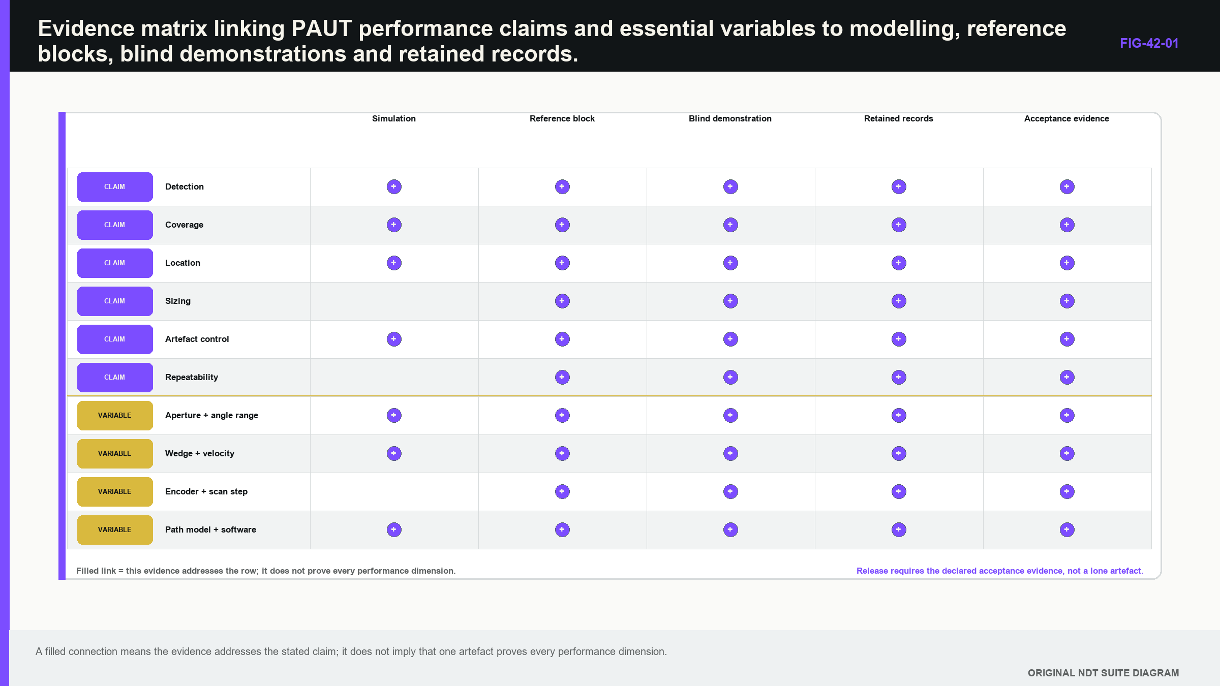
Notice that a populated row for detection can coexist with an empty row for sizing. A large qualification file is not complete merely because it contains many pages.
42.3 Refresh the evidence layers before choosing tests
Qualification becomes easier to reason about when evidence is arranged in layers. Engineering analysis explains the mechanism. Models explore coverage and sensitivity. Reference blocks establish controlled responses and measurement function. Representative specimens test application behaviour. Blind trials challenge the frozen technique and decision process. Production controls maintain the released state.
No single layer replaces the others. A field calculation can examine many focal-law combinations quickly but may simplify target scattering. A representative weld includes real coupling and geometry but samples only a limited set of targets. A blind trial reduces confirmation bias but cannot reveal every untested variable. The claim is supported by the connected package.
For the weld case, the team first uses geometry and field models to select probe position, angle range, aperture and focus. It then checks timing, coverage and target response on controlled blocks. Representative specimens include thickness limits, fusion-face orientations, relevant surface states and known geometry features. Robustness trials vary placement, coupling and reconstruction within controlled bounds. Only after the design and decision rule are frozen are independent blind cases opened.
The evidence matrix should name the contribution and limit of every item. “Simulation” is too vague. “Verified field model used to compare relative coverage at thickness endpoints, validated against field-map position and width over the released angle range” is inspectable. “Successful practical” is too vague. “Blind target-level detection and false-call results under the frozen rule” states what was observed.
42.4 Use models for exploration, then prove what their output means
Models are valuable because they reveal likely gaps before expensive specimens are built. They can compare probe offset, active aperture, steering range, focus depth, wedge wear and component geometry. The Level 3 must identify the model output: nominal ray intersection, acoustic-pressure proxy, pulse-echo response or simulated waveform.
Verification checks that the equations and software are solved as intended. Useful evidence includes benchmark geometry, convergence with mesh or step refinement, comparison with an independent calculation and regression against known cases. Validation checks whether the model represents the relevant physical behaviour. It compares predicted arrival time, beam direction, focal position, field width or target response with measurements appropriate to the intended use. Computational NDE guidance keeps these activities distinct because correct software can still implement an inadequate physical model. [R036] [R037] [R038]
For the continuing case, a ray model may verify path access and wedge clearance. A field model may compare angular and depth support. If the qualification argument relies on modelled relative amplitude, measured field or target-response comparisons are needed across the claimed range. Colour contours without units, normalisation and assumptions are design pictures, not stand-alone qualification evidence.
Model inputs should span credible variation. Material velocity, wedge thickness, probe offset, surface curvature, element response and weld preparation may interact. Running only the nominal values demonstrates the centre of the design, not its resilience. The output metric should also match the claim. A maximum pressure value can remain high while the useful field shifts away from the target region.
The model record includes version, equations or method, geometry, material properties, array definition, boundary conditions, numerical controls, normalisation, output metrics and known limitations. Inputs fitted to one specimen are marked as calibrated. That specimen cannot then be presented as independent validation of the same fitted behaviour.
42.5 Build specimens around physical representativeness
A representative specimen contains the material, geometry, surface and target features that materially affect the claim. Exact copies of every production weld are rarely possible. The task is to identify which features must be present, which can be bounded by analysis and which become exclusions.
Machined reflectors have important strengths. Side-drilled holes give repeatable timing and comparative sensitivity. Notches provide known planar orientation and dimensions. Yet their smooth geometry and known position can respond differently from rough service or fabrication discontinuities. Embedded flaws and realistic weld imperfections improve morphology but make reference truth harder to establish. A useful programme combines target types instead of asking one reflector to impersonate the entire defect population.
The weld case therefore uses controlled reflectors for setup function, planar notches near the fusion faces for orientation sensitivity, and representative embedded or fabrication flaws where available. Non-target geometry is included deliberately. Root, cap, counterbore, backing or nearby fusion-face responses test false-call control rather than being edited out of the demonstration.
Truth data are registered in the same component frame as PAUT results. Target location and size are established by manufacturing records, metrology, complementary high-resolution NDT or sectioning, as appropriate. Their uncertainty and any alignment transformation remain in the package. When destructive sectioning changes the reference surface, the transformation back to the inspection frame is part of the truth model.
Representativeness is output specific. A block may be suitable for timing but not structural noise. A notch may challenge detection orientation but not crack-tip sizing. A specimen can be representative of thickness and geometry while remaining unrepresentative of material attenuation. The qualification report should say which use each specimen supports.
42.6 Derive essential variables from the way performance can fail
An essential variable is a factor whose change can materially affect a claimed output. The list should come from the physical and measurement models, observed failures and evidence, not from copying another technique table.
For the weld case, equipment variables include array, wedge, frequency band, pitch, aperture, focal-law delays and weights, angle, focus, scanner and coupling. Application variables include probe offset, scan direction, material, velocity range, thickness, surface, weld geometry and calibration. Software, reconstruction, analysis rule and personnel competence complete the candidate set.
Some variables are ranges. Material velocity and thickness can be bounded continuously. Some are alternatives, such as approved probe models or scanning directions. Some remain controlled identities until equivalence is shown, such as focal-law generator or analysis software build. A version number is not mere paperwork when it controls coordinates or delay calculation.
Interactions matter. Pitch acceptability depends on wavelength and steering. A focal setting may be robust in isotropic parent steel and fragile in a textured weld. Probe offset and surface curvature can combine to shift the insonified volume. Testing every factor separately can miss those coupled failures.
The evidence matrix records how each range is supported. Endpoints may be tested. Sensitivity analysis may support interpolation. A fixed identity may be locked because no equivalence evidence exists. A variable table without these links is administrative wallpaper, neat enough to frame and just as technically useful.
42.7 Challenge the nominal setup with robustness work
Robustness asks whether the technique remains adequate when normal work is not perfectly nominal. The objective is not to abuse the system randomly. It is to vary plausible factors through declared ranges and observe the performance mechanisms.
Begin with the failures that matter. Probe placement error can reduce fusion-face support. Wedge wear can alter delay and angle. Coupling variation can reduce amplitude or create spatial gaps. Velocity change can bias coordinates. Element degradation can distort the aperture. Encoder slip can stretch the image. A rebuilt setup can expose undocumented expert adjustments.
One-factor-at-a-time trials help explain individual effects. Designed combinations or sampled simulations are needed where interaction is credible. The chosen outputs should include detection, localisation, field position, signal-to-noise ratio (SNR), morphology, sizing bias, false calls and data completeness. Peak amplitude alone can reward an unwanted lobe or geometry echo.
Human variation belongs in the study. Different operators mount and scan the probe. Different competent analysts apply the frozen rule to blinded data. The setup is rebuilt from controlled records on another day or workstation. Repeatability under the same conditions and reproducibility under changed conditions answer different questions.
Suppose detection remains stable across the 20–40 mm range but location error increases near 40 mm after a velocity and wedge-temperature combination. The correct conclusion is not that the technique passed because every target was seen. Detection may remain supported while the location range, compensation or uncertainty model needs change. Qualification keeps outputs separate precisely so one success cannot hide another failure.
42.8 Freeze the design before blind confirmation
A blind trial hides target truth from the people making acquisition and analysis decisions. It reduces the natural tendency to search harder where a target is known and to explain away an unexpected response. Independence, training cases, randomisation, allowable rescans, indeterminate calls and protocol deviations should be controlled before the trial starts.
Development and confirmation data serve different purposes. Probe position, laws, thresholds and decision rules are tuned on development cases. Confirmation cases remain unseen until the design is frozen. If confirmation exposes a weakness, the team may redesign the technique, but those cases have then joined development. A new independent confirmation set is needed for the revised claim.
The simplest trial summary is the observed hit fraction. Physically, it is just the number of applicable targets called detected divided by the number presented. It describes that trial; it does not predict a general probability across untested flaw sizes or conditions.
| (42.1) Observed hit fraction · EQ-42-01 Where: p_hat = observed hit fraction in the stated trial, dimensionless; n_hit = number of applicable targets detected by the defined decision rule, count; n_target = number of applicable targets presented, count Model limits: target truth and applicability are established; every target has one controlled outcome; this descriptive fraction is not by itself a POD curve or confidence statement |
|---|
This relationship has no units because it divides one count by another. It says nothing about which target sizes were missed. A 90% fraction made from easy large targets can support less than a lower fraction from a deliberately difficult representative population.
POD analysis requires a defined target population, a flaw-size or response model where appropriate, enough observations, a suitable hit-miss or signal-response method and confidence bounds. A small all-hit demonstration can still leave substantial statistical uncertainty. POD guidance should therefore be used for its full reliability framework, not as a label attached to a percentage. [R033] [R034]
42.9 Read hits, misses and false calls together
The continuing weld trial contains 30 applicable targets spanning size, depth, orientation and thickness. The frozen decision process finds 27, misses 3 and reports 5 non-target geometry responses as relevant. The descriptive calculation is useful, but the failure pattern is more useful.
| Worked example · Why a blind hit fraction is not a POD claim WE-42-01 Given: A blind trial contains 30 known targets spanning several sizes and positions. The defined decision process detects 27 and misses 3. Five non-target geometry features are also reported as relevant. Find: Calculate the observed target hit fraction and identify the evidence still missing from a POD claim. Steps: Divide detected applicable targets by presented applicable targets: p_hat = 27 / 30 = 0.90. As a rough indication of sampling spread, sqrt(0.90(0.10)/30) = 0.055. This standard-error scale is not a fitted POD curve or a formal confidence bound. Retain the three miss conditions and five false calls beside the fraction. Answer: The stated trial observed a 0.90 hit fraction, or 90%, with three misses and five false calls. Technical implication: The result must be interpreted with target-size distribution, confidence treatment, decision-rule control, independence and false-call behaviour. It cannot support a universal “90% POD” statement. Common mistake: Reporting 27 of 30 as 90% POD and omitting the target population, misses, false calls and uncertainty. |
|---|
The failure and substitution case is revealing. If the three misses all occur on near-fusion-face targets at the thick limit, they identify an angular or field-support boundary. Increasing gain may brighten other responses without correcting that mechanism. If the false calls cluster at a root geometry feature, the analysis rule or complementary view needs work.
A trial can raise its apparent hit rate by declaring every response relevant. Reliability therefore considers detection and false indications together. Record target-level results, non-target calls, indeterminate outcomes, rescans and invalid cases under rules written before truth is opened.
42.10 Keep negative and abnormal cases in the evidence package
Unsuccessful runs are technical evidence. Poor coupling, dropped frames, setup errors and reader disagreement show how the system fails and how production controls should detect the condition. They should not be removed merely because a later attempt succeeded.
An exclusion can be legitimate when a predeclared validity rule is breached. For example, a scan with documented encoder loss may be invalid for the performance trial. The record still retains the raw case, reason, decision authority and effect of excluding it. Repeating until a favourable set remains would bias the result.
Analyse each failure by mechanism. A missed target caused by absent angular support requires design change. A wrong coordinate caused by registration requires metrology correction. A false call caused by geometry may require another view or controlled rule. A clipped waveform cannot be repaired by post-processing. Grouping all failures as “operator error” prevents useful corrective action.
Qualification criteria should be written before confirmation data are opened. They may address valid-case fraction, target detection, coordinate tolerance, sizing error, false calls, data completeness and allowed indeterminate results. Predeclared rules stop the goalposts from quietly developing wheels.
42.11 Transfer only the functions shown to be comparable
The qualified weld technique is now moved to a nominally similar instrument at another site. The probe label and setup file match, but this alone does not establish equivalence. Pulsers, receivers, digitiser timing, channel matching, probe manufacture, wedge geometry, focal-law implementation and display processing can differ.
Transfer begins by asking which functions support each claim. Timing and coordinate comparisons support location. Element and field comparisons support angular coverage. Raw amplitude and reference-target comparisons support comparative sensitivity. Representative target scans challenge the combined result. Analyst reproducibility tests the decision process.
Bridge evidence may include equipment characterisation, delay comparison, field mapping, reference scans, raw-data comparison and repeated performance cases. A palette-only change may need little evidence. A different probe, focal-law engine or reconstruction path can require substantial revalidation.
Commercial advanced-NDE demonstrations and comparisons are useful only within their specimens, systems and metrics. They are not universal vendor rankings and do not qualify this weld application. [R061] The transfer conclusion should therefore be output specific: detection may remain comparable while coordinate or sizing performance requires further work.
42.12 Build a claim-led report and maintenance plan
The qualification report should allow an independent reviewer to travel from each claimed output to its evidence. For every claim it lists the requirement, component and target population, decision rule, essential variables, analytical or model basis, specimen truth, robustness work, confirmation result, uncertainty, limitation and retained data identity.
Model-supported coverage, experimentally demonstrated response and statistically estimated reliability are named separately. Raw data, setup files, law files, model inputs, result tables and deviations remain traceable. Supported ranges and exclusions appear in the conclusion rather than being buried in an appendix.
Qualification continues after release. Periodic checks, proficiency, software regression, calibration assurance and abnormal-event review maintain the evidence chain. Field experience may reveal a false-call population or adverse geometry absent from development. That information updates the risk, model and validation plan instead of remaining informal operator folklore.
The boundary between maintenance and requalification follows the affected mechanism and claim. Restoring a characterised cable may need bounded functional evidence. Replacing the probe architecture, law generator or component population can reopen several claim rows. Governance in Chapter 45 will formalise this reasoning.
42.13 Review the weakest supported case
A broad range is not qualified by its easiest central specimen. The review should identify combinations that place the greatest demand on the technique: adverse depth, orientation, access, curvature, attenuation, nearby geometry, placement tolerance or noise.
The weakest case may involve several coupled variables that no single specimen contains. The evidence matrix can separate mechanisms across model and specimen work, provided the links back to the complete claim remain explicit. Interpolation is defensible only where the effect is understood and bracketed. Extrapolation is a new claim.
An independent sufficiency review asks what credible failure could still pass every test performed. An untested sparse orientation, software default, geometry echo or operator workaround can remain invisible inside an otherwise polished package. Add a challenging case or narrow the claim until that failure no longer hides between the rows.
Evidence ownership matters here. The organisation responsible for the technique needs access to raw datasets, target truth, model inputs and decision records. A vendor certificate or demonstration summary can contribute, but cannot replace inspectable evidence for the exact configuration and claim. [R061]
42.14 Evidence boundary for the continuing weld case
At release, the continuing case supports detection and location of its declared planar-target population over the evidenced ferritic weld range. Height sizing is supported only when two qualified tip responses are resolved within the demonstrated range. The report retains observed misses, false calls, truth uncertainty and cases where the result is indeterminate.
It does not claim universal PAUT capability, all weld materials, all planar flaws or automatic POD. It does not export the result to another probe or software build without transfer evidence. These boundaries are not weaknesses in the report. They are the reason a future reviewer can understand what remains valid after a change.
In plain words
- Qualification proves a bounded inspection claim, not a method name.
- Detection, location, sizing and false-call control require distinct evidence.
- Models explore mechanisms, while specimens and blind trials challenge real performance.
- Verification checks the calculation; validation checks physical representation.
- Representative targets include difficult targets and confusing non-target geometry.
- An observed hit fraction is not automatically a POD curve.
- Misses and false calls reveal design limits and belong in the record.
- Transfer and maintenance repeat evidence according to the affected claim.
Formal synthesis
PAUT qualification is a claim-led evidence argument for a defined inspection system and target population. Measurable outputs, reference truth and decision rules determine what can be tested. Verified and validated models support coverage and sensitivity within declared assumptions. Representative specimens, essential-variable studies and blind confirmation expose application, interaction and human dependencies. Reliability results retain misses, false calls and statistical limits. Transfer, maintenance and sufficiency review preserve only those outputs whose supporting mechanisms remain comparable.
Key terms
- Qualification: evidence that a defined system meets a bounded claim.
- Essential variable: factor capable of changing qualified performance.
- Verification: confirmation that a model is solved correctly.
- Validation: evidence that a model represents the needed physical behaviour.
- Robustness: maintained performance under credible variation.
- Blind confirmation: independent challenge after design and decision rules are frozen.
- Evidence boundary: limit beyond which the qualification result is not supported.
Key relationships
- EQ-42-01 describes the hit fraction observed in one stated trial.
- Performance evidence belongs to a system, population, output and range.
- Model verification and model validation address different failure mechanisms.
- Detection fraction must be interpreted with target distribution, confidence and false calls.
Common mix-ups
- A successful block demonstration is not a universal qualification.
- Geometric ray coverage is not demonstrated detection reliability.
- A hit fraction is not automatically POD.
- A nominally similar system is not automatically equivalent.
- Repeated confirmation cases become development data after the design is changed to fit them.
Bridge to Chapter 43
Chapter 42 assumed that the propagation model was adequate within a ferritic weld range. Chapter 43 examines what appears on the screen when that assumption fails in anisotropic, coarse-grained, layered, clad, curved and strongly heterogeneous components, and shows how evidence should grow before model complexity does.
Sources and further study
- [R033]
- [R034]
- [R036]
- [R037]
- [R038]
- [R061]
Study and revision only. This is not an approved inspection procedure, acceptance criterion or qualification.