
CHAPTER 13 · Phased Array Ultrasonics Level 2
Calibration Strategy and Reference Standards
In this chapter · 11 sections
Learning outcomes
After completing this chapter, the learner should be able to:
- distinguish laboratory instrument calibration, user setup calibration, reference sensitivity and routine performance checks;
- arrange PAUT setup activities in a technically sound dependency order;
- select a reference standard that is suitable for the intended measurement or response;
- explain the uses and limitations of radii, side-drilled holes, flat-bottom holes, notches and system-assessment targets;
- compare DAC, TCG and DGS without treating any of them as direct measurements of a real discontinuity;
- identify the evidence needed to accept a setup for use; and
- recognise when a calibration result is invalid because its assumptions do not represent the examination.
Key terms
Calibration; standardisation; reference standard; calibration block; reference reflector; representative material; sound path; side-drilled hole (SDH); flat-bottom hole (FBH); notch; reference sensitivity; angle-corrected gain; distance-amplitude correction (DAC); time-corrected gain (TCG); distance-gain-size (DGS); equivalent reflector; verification; traceability.
13.1 Why calibration needs a strategy
A PAUT setup contains several linked models. The instrument must know how quickly sound travels in each medium, where the probe elements sit relative to the component, how the wedge changes the beam path, which elements form each aperture, and what timing is required for each law. It must then relate echo time to position, echo amplitude to a reference response, and encoder movement to distance along the component.
Those relationships cannot be established in a random order. An excellent amplitude calibration built on the wrong wedge velocity is still an excellent calibration of the wrong beam. Increasing gain or completing a wedge-delay wizard does not repair a wrong refracted angle, an incorrect element position or a scan plan that misses part of the examination volume.
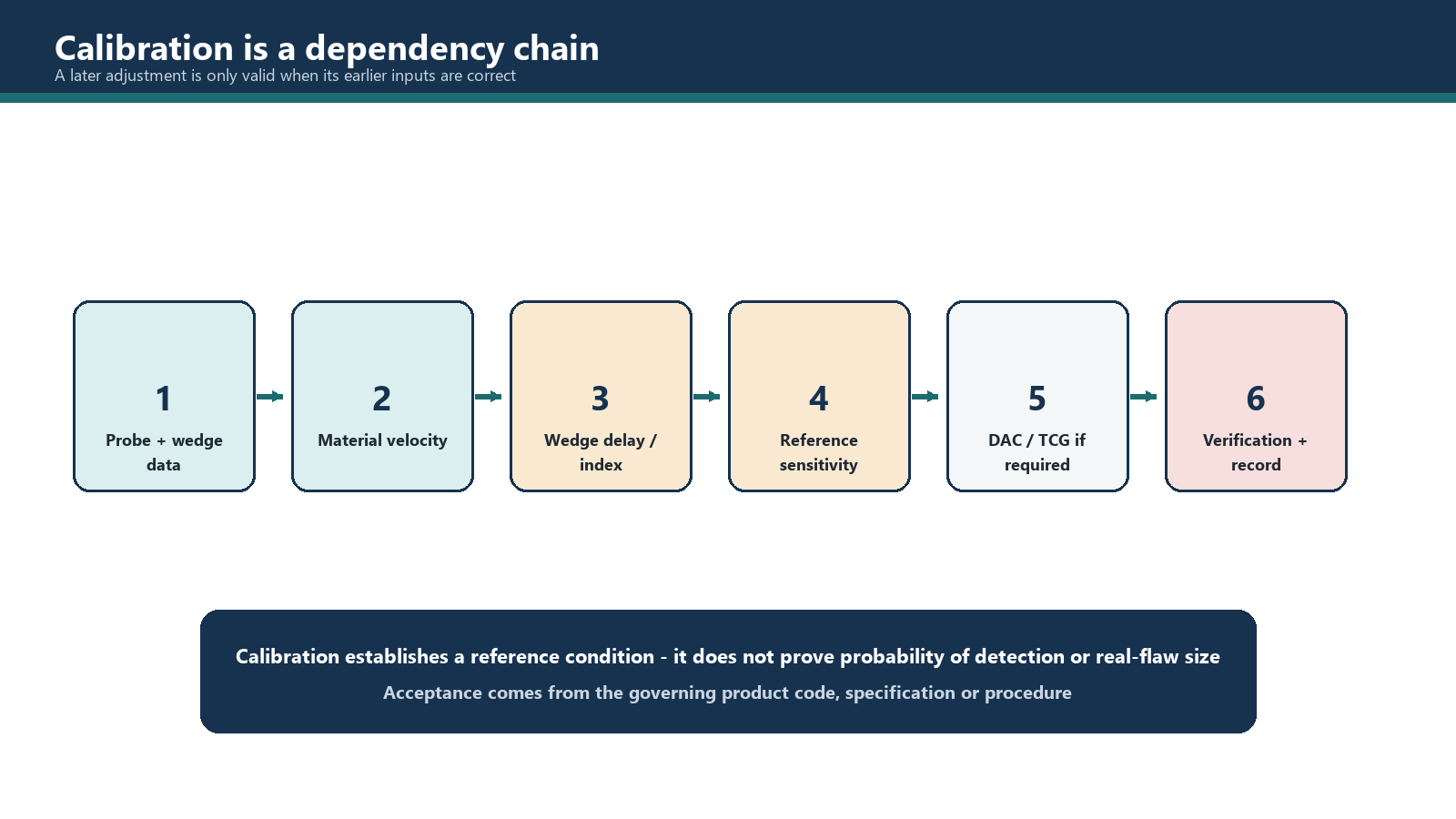
A useful calibration strategy follows the dependency chain:
- confirm the governing procedure, technique and acceptance source;
- identify the component, material, geometry, temperature range and examination volume;
- confirm the instrument, probe, wedge, cable, scanner and encoder identities;
- enter and verify the material, probe and wedge data used to calculate the focal laws;
- generate the required law groups and check their coverage;
- establish time and distance relationships, including material velocity and wedge delay where required;
- establish amplitude relationships, including law-to-law sensitivity and distance compensation where required;
- calibrate positional devices used for encoded collection;
- verify the complete setup against independent known features; and
- record and protect the accepted configuration.
The exact sequence and terminology may differ between procedures and instruments. The dependency does not: inputs used to calculate focal laws must be correct before later corrections can be trusted.
13.2 Four activities that are often called “calibration”
The word calibration is used loosely in day-to-day NDT. That can hide important differences in responsibility and evidence. This manual uses the following practical distinctions; the organisation's controlled quality system remains authoritative.
Laboratory or service calibration
This activity evaluates measuring equipment against traceable references, normally at specified intervals and after repair. It may cover time-base accuracy, gain control, pulser behaviour or encoder interfaces. A service certificate supports confidence in the instrument, but does not validate a particular probe, wedge and law set; field setup likewise does not replace required service calibration.
User setup calibration or standardisation
This relates the assembled system to known paths, depths, positions or amplitudes. It includes velocity, wedge-delay, sensitivity, DAC, TCG and encoder work for the actual instrument, probe, wedge, cable, settings, block and scanner combination.
Reference sensitivity
Reference sensitivity establishes a repeatable artificial-reflector response for comparison. It does not demonstrate the smallest real flaw that will always be found. Detection also depends on reflector orientation and morphology, surface condition, coupling, noise, coverage, scanning, data quality and analysis.
Performance or stability check
A performance check compares current behaviour with an accepted baseline and controlled tolerance to detect drift, damage, encoder error, failed elements or changed settings. Its timing is defined by the governing requirements.
13.3 The reference standard must answer the right question
No single block proves every property of a PAUT examination. A block is selected because one or more of its features have known dimensions or acoustic responses. Before using it, ask: What relationship am I trying to establish?
Purpose
A reference standard may establish or verify:
- a known sound path or depth;
- material velocity;
- a wedge-delay or time-zero relationship;
- response across focal laws or steering angles;
- amplitude variation with distance;
- beam position, angle, width or resolution;
- encoder distance; or
- system performance against a baseline.
Prerequisites
Before use, confirm:
- the block identity and drawing revision;
- the applicable procedure or course requirement;
- material type, acoustic condition and temperature relevance;
- surface condition, curvature and coupling condition;
- the dimensions and orientation of the selected target;
- that the sound path and target location cover the intended examination range;
- that the target can be reached by all laws being calibrated; and
- that no competing reflector enters the measurement gate.
“Made of steel” is insufficient where velocity, attenuation, structure or anisotropy affects the result. The procedure defines the required material and geometry representation.
Method
Use the feature only for its controlled purpose. Maximise the intended response with stable coupling and show that every included law interacts with that target rather than a competing echo.
Acceptance evidence
Evidence shows the known and measured values, residual error, included laws and tolerance source. A completed wizard alone is insufficient.
Common failure modes
- selecting a convenient target rather than a relevant one;
- using a block with an unverified identity or damaged surface;
- measuring a different echo from the one assumed;
- allowing a notch or corner response to vary with angle while treating it as angle-independent;
- using a target outside the useful depth or sound-path range;
- calibrating only part of the law set without recording the excluded laws;
- allowing temperature or couplant changes to alter the response; and
- assuming the artificial reflector responds like a service-induced discontinuity.
Records
Record the block and drawing ID, target, material, conditions, orientation, law range, gate, result, tolerance and status.
13.4 Common target families
Known radii and back-wall paths
A machined radius or a back wall can provide a known sound path. Two separated known paths are useful for determining material velocity while reducing the influence of an unknown time offset. A radius can also support wedge-delay or angle checks when the procedure and geometry make it suitable.
A smooth radius is not a flaw simulator. Its main value is geometric: the path to the reflecting surface is known. The operator still has to maximise the correct response and understand whether the instrument is displaying sound path, true depth or another corrected coordinate.
Side-drilled holes
An SDH is a controlled cylindrical reflector used for response comparison, law sensitivity, DAC/TCG, beam characterisation and some angle checks. Its response depends on orientation, path and beam dimensions.
An SDH should not automatically be described as equivalent to a crack of the same diameter. The geometry and reflection mechanism are different. The hole provides a reproducible reference response, not a direct portrait of a real flaw.
Flat-bottom holes
An FBH presents a flat circular face and is useful for area-amplitude work or a reference normal to the beam. Sets may vary diameter at a common distance or hold diameter constant at different distances.
The face must be appropriately oriented to the beam. A strong FBH response does not establish that a misoriented planar discontinuity will produce the same amplitude. DGS and equivalent-reflector methods may express an unknown echo as an equivalent FBH response, but that result is an acoustic comparison under stated assumptions—not a physical measurement of the discontinuity's actual diameter.
Notches and surface-connected targets
Notches can represent a controlled surface-breaking reflector and may be required by a governing procedure. They are strongly orientation-sensitive. A notch that is effective for a single nominal angle may not provide a uniform response throughout a wide sector. It should therefore be used only for the purpose, beam directions and technique for which it is specified.
System-assessment targets
Multi-target assessment blocks can evaluate resolution, steering, focusing or element performance. They support qualification and baselines, but replace inspection-specific setup calibration only when the governing procedure says so.
Course-nominated standard blocks
The course may require blocks identified by controlled Australian block designations, including commonly named Block 1, Block 2 or miniature block forms. The student should learn the purpose and safe use of the nominated features. Dimensions and formal requirements must be taken from the controlled standard or approved drawing supplied for the course. A textbook sketch is explanatory only and must not become an uncontrolled manufacturing drawing.
13.5 Matching the block to the examination
Matching depends on the measurement. Acoustic properties may be irrelevant to an encoder-distance check but central to velocity and amplitude comparison. Curvature, surface, coupling and anisotropy may also matter. Document why the block is suitable and any authorised correction, transfer assessment or limitation. Quietly hoping the sound will not notice is not a technical control.
13.6 DAC, TCG and DGS
These tools address related amplitude questions but present the result differently.
Distance-amplitude correction
A DAC curve plots defined reference responses at different paths/times without applying the curve as gain. It leaves the changing reference level visible for indication comparison; reflector selection and comparison rules come from the procedure.
Time-corrected gain
TCG applies gain versus time/path to bring selected reference responses toward a common level, potentially across multiple laws.
TCG equalises the chosen reference reflectors under the calibration conditions. It does not make equal-sized real discontinuities return equal amplitudes. Crack orientation, roughness, curvature, tip response, beam incidence, local attenuation and coupling remain influential. TCG also does not cure missing coverage or an incorrect focal law.
Excess correction can raise noise, reduce dynamic range or saturate signals. Reference points must cover the qualified range, including checks between and near its limits.
Distance-gain-size
DGS compares an echo with ideal-reflector responses and may express an equivalent reflector size. It depends on probe, beam, attenuation and coupling assumptions and is not a direct flaw-dimension measurement.
Selecting among them
The governing procedure determines which method is allowed and how the reference is used in evaluation. A modern instrument may be able to display related DAC and TCG representations from the same calibration data, but the examiner should not assume that every implementation is mathematically or procedurally interchangeable. The chosen method must be verified in the mode in which the data will be collected and analysed.
13.7 Accepting the calibration strategy
A strategy is ready for use when the following evidence exists:
- all equipment and reference-standard identities are controlled;
- focal-law inputs and scan-plan coverage have been checked;
- each required measurement has a suitable reference feature;
- the relevant law, angle, depth and sound-path ranges are included;
- tolerances and recheck frequencies come from the governing procedure, standard or manufacturer requirement;
- independent verification targets agree within those limits;
- unresolved limitations are recorded and authorised; and
- a record identifies exactly which saved setup was accepted.
Completion of a software wizard is not, by itself, acceptance evidence. The final question is not “Did the instrument say done?” It is “What known relationship did we establish, over what range, and how do we know it remains valid?”
Common traps
- Treating a service certificate as proof that the inspection setup is correct.
- Treating a reference reflector as the smallest detectable flaw.
- Selecting a different material because its block is convenient.
- Using one reflector orientation across a sector without checking angular response.
- Building DAC or TCG before law-to-law sensitivity is established.
- Extending a curve beyond its calibrated reference range.
- Quoting a tolerance from memory without a controlled source.
- Calling an equivalent reflector size the actual flaw size.
Chapter summary
Calibration is a chain of controlled relationships: validate component, material, probe, wedge and law inputs; establish time, distance, amplitude and position; then verify the assembled system. Select reference standards for the question they can answer. DAC displays a distance-dependent reference, TCG applies time-dependent gain, and DGS provides an equivalent-reflector comparison. None proves probability of detection or directly sizes a real discontinuity.
Study and revision only. This is not an approved inspection procedure, acceptance criterion or qualification.