
CHAPTER 14 · Phased Array Ultrasonics Level 2
Calibrating a PAUT Setup
In this chapter · 13 sections
Learning outcomes
After completing this chapter, the learner should be able to:
- prepare a PAUT group for calibration without relying on a saved setup of unknown origin;
- determine or verify material velocity using suitable known paths;
- verify probe and wedge data before calculating focal laws;
- perform and independently verify wedge-delay calibration;
- establish law-to-law reference sensitivity;
- construct and verify DAC or TCG over the required range;
- recognise changes that invalidate part or all of a calibration; and
- produce a complete calibration record.
Key terms
Group; focal law; material velocity; wedge velocity; wedge geometry; element position; index point; exit point; time zero; wedge delay; reference amplitude; gain offset; angle-corrected gain; envelope; gate; DAC; TCG; verification target; residual error; calibration validity.
14.1 The setup is an identified system
A PAUT calibration belongs to an identified combination, not merely an instrument file. It includes:
- instrument and software configuration;
- probe model and serial number;
- wedge model, serial or unique ID, and condition;
- cable and any adaptor;
- pulser, receiver, filter, rectification and averaging settings;
- material and wedge velocities used by the focal-law calculation;
- element positions, wedge dimensions and offsets;
- group definition, aperture, law count, angles and focal settings;
- calibration/reference block and target;
- couplant and surface condition; and
- encoder/scanner configuration when position data will be recorded.
Every change requires an impact decision. A wedge, geometry or velocity change may require new laws and full recalibration; an amplitude-filter change may invalidate sensitivity and DAC/TCG but not encoder scale. The procedure defines the response.
14.2 Preparation and prerequisites
Purpose
Begin with a sound assembly and approved examination design so calibration cannot hide a setup error.
Prerequisites
Confirm:
- the procedure, technique sheet or approved scan plan is available;
- the examination volume, coordinate system, reference datum and required coverage are understood;
- probe and wedge identities match the approved design;
- the wedge contact face is clean and not worn beyond its permitted condition;
- cables, connectors and strain relief are sound;
- the instrument has completed any required warm-up and self-check;
- material and wedge data are from controlled sources or approved measurements;
- the reference block is identified, clean, undamaged and at a relevant temperature;
- the selected targets cover the required law and sound-path range; and
- the data range, gates and display are set so that the intended echoes can be observed without clipping.
Method
Compare every important group input with the approved setup sheet, including dimensions, element orientation, first-element reference and offsets. A database name is not verification. Scan the reference target to confirm plausible paths, law coverage, coupling and element response before applying corrections.
Acceptance evidence
Trace every input to the technique, manufacturer data, controlled measurement or authorised custom-wedge record. The target must appear where expected before correction.
Failure modes
- loading a setup created for a similar but different wedge;
- reversing probe orientation or element order;
- using an incorrect longitudinal/shear velocity;
- selecting the wrong material or wave mode;
- applying a saved calibration after a law group has changed;
- calibrating through unstable coupling or a damaged contact face; and
- using saturated or competing echoes.
Records
Record the equipment chain, setup ID, group, reference target, conditions and source of custom values.
14.3 Material velocity
Material velocity converts time into path and supports angle/focal-law calculations. It is not universal: mode, composition, structure, texture, temperature and direction can matter, especially in anisotropic material.
Purpose
Establish or verify the velocity used for the selected wave mode and representative acoustic path.
Prerequisites
- a representative material or an approved basis for using a nominal value;
- one or preferably two accurately known sound paths or thickness-related echoes;
- stable coupling and a law suitable for the measurement;
- a time range that clearly separates the selected echoes; and
- correct units and wave mode.
Method
Where practical, maximise echoes from two separated known paths so propagation time can be distinguished from fixed delay. Use one suitable stable law, consistent coupling and the procedure-specified geometry. Calculate velocity, then verify it on another known feature or by rechecking both paths.
If the velocity used to create the focal laws changes, rebuild the affected groups before continuing. A later wedge-delay adjustment cannot correct a refracted angle or focus calculated with the wrong material velocity.
Acceptance evidence
Accept on agreement between known and measured paths within the controlled limit, including residual errors across the relevant range—not just the displayed velocity.
Failure modes
- measuring a dissimilar block and applying the result to the component without authorisation;
- mixing longitudinal and shear paths;
- measuring the wrong multiple echo;
- using one point where delay is not already known;
- averaging measurements from strongly different directions in an anisotropic material;
- accepting a value because it is close to a database default; and
- changing velocity without regenerating laws and clearing dependent calibrations.
Records
Record material, mode, direction, conditions, known paths, observations, velocity, residual errors and affected groups.
14.4 Probe, wedge and index information
The focal-law calculator uses wedge angle/velocity/dimensions, roof angle, element position/orientation and offsets. A custom or worn wedge may not match its catalogue model.
Wedge velocity varies with material and temperature. Use the controlled value required by the procedure or the approved method for determining it. Do not mix nominal values within one calculation. If a worked example uses 2,320 m/s, every line of that example must use 2,320 m/s—not 2,330 in the introduction and “about 2.3” when the answer is inconvenient.
Exit position can migrate between laws as rays cross the interface at different locations. Corrected coordinates are only as reliable as the inputs; required physical alignment checks still apply.
14.5 Wedge-delay calibration
Wedge-delay calibration compensates the timing contribution between element excitation/reception and the chosen component-surface reference. In a sector or stepped-aperture group, different laws may have different wedge paths and therefore different corrections.
Purpose
Align a known target with its correct path/depth for every included law after geometry and velocities are verified.
Prerequisites
- verified probe, wedge, material and focal-law inputs;
- a suitable known path or depth target accessible to all included laws;
- a stable gate that contains the intended response and excludes competing echoes;
- adequate range for the complete law set;
- consistent coupling and contact pressure; and
- any required sensitivity sufficient to observe the target without saturation.
Method
- Position the probe so the selected target is visible throughout the law range.
- Confirm that each law can reach the target and that the displayed path trend is physically plausible.
- Clear any previous peak-hold or envelope used by the routine.
- Move the probe smoothly so that the target response is maximised for each law. The aim is to collect the target's peak position, not merely any signal inside the gate.
- Apply the calculated delay corrections to the selected law range.
- Repeat the movement and observe the residual path/depth error.
- Accept the correction only when the residual error meets the controlled tolerance.
Acceptance evidence
The target must report at the required path/depth across included laws within the controlled tolerance. Save the law range, target and residual errors; an independent verification feature is stronger than replaying the same data.
What wedge delay cannot fix
Wedge-delay calibration cannot correct:
- the wrong material velocity;
- the wrong wedge velocity used to form the laws;
- an incorrect wedge angle, height or element position;
- a probe mounted backwards;
- an incorrect refracted-angle range;
- a focus calculated at the wrong location; or
- a damaged wedge that changes contact and geometry unpredictably.
If timing cannot align a known reflector, investigate geometry, velocity, element order and laws. Repeatedly pressing “calibrate” only makes the same mistake more confident.
Failure modes
- an over-wide gate capturing another reflector;
- incomplete target coverage at the extreme laws;
- erratic hand pressure or couplant loss;
- calibrating in sound-path mode and verifying as true depth without understanding the conversion;
- accepting a partial law range as a complete group; and
- failing to clear dependent calibration after changing wedge data.
Records
Record target, dimension, law range, gate, coordinate, limit, residual errors, exclusions and verification.
14.6 Law-to-law sensitivity
A reference target varies across laws because of elements, wedge path, transmission, angle, aperture and coupling. Sensitivity correction applies per-law gain offsets to control that chosen response.
Purpose
Establish a common reference response across the laws used for detection and amplitude evaluation.
Prerequisites
- completed time/path calibration;
- a target suitable for the angle and aperture range;
- a reference level and tolerance from the approved procedure;
- stable coupling and a gate that isolates the target;
- no saturated laws; and
- sufficient range to maximise the target on every included law.
Method
Traverse the target to record each law's valid maximum. Review gaps, competing echoes and outliers before correction. Choose base gain to avoid clipping or exhausted gain, apply offsets, repeat the traverse and verify.
Acceptance evidence
Responses must fall within the controlled band. Retain offsets and the verification envelope; investigate unusual corrections.
Limitations
This process equalises one selected reference response across laws. It does not establish a minimum detectable flaw, correct missing beam coverage, compensate for every flaw orientation or guarantee that an arbitrary discontinuity produces the same amplitude at each angle.
Failure modes
- using an orientation-sensitive notch across a broad sector without qualification;
- allowing a competing echo to set the peak;
- calibrating at a depth unrelated to the examination volume;
- applying excessive offsets to a weak or damaged element;
- changing filters, pulser voltage, aperture or averaging afterwards; and
- confusing angle correction at one depth with distance compensation through the full range.
Records
Record target, reference level, tolerance source, base gain, included laws, per-law offsets, outliers, verification band and final status.
14.7 Building DAC or TCG
Distance compensation follows law sensitivity: first align the chosen response across laws, then establish its change through the required path range.
Purpose
Create the approved amplitude reference versus distance, either as a displayed DAC curve or as applied TCG.
Prerequisites
- completed velocity, wedge-delay and sensitivity work;
- reference targets of controlled size and orientation at suitable paths;
- reference points that cover the evaluation range;
- gates that isolate each target;
- adequate gain and dynamic range; and
- a procedure defining the method, reference level and permitted interpolation/extrapolation.
Method
- Select the approved DAC or TCG mode.
- Establish the first valid reference point across the required laws.
- Move the gate to the next target and acquire its maximum response for each included law.
- Continue in increasing path order until the required range is covered.
- Inspect each curve or correction for abrupt steps, excessive gain, missing laws and implausible trends.
- Verify the reference targets after the curve is complete.
- Check at least one intermediate or independent target where the procedure requires it.
- Confirm behaviour at the near and far limits of the evaluation range.
For TCG, check noise and saturation; for DAC, confirm the correct curve is active during analysis. Do not exceed the supported range without authorisation.
Acceptance evidence
Required points and laws must meet the controlled tolerance without unapproved gaps, remain within system capability and preserve dynamic range. Record the valid range.
Failure modes
- too few points to represent the required range;
- reference points concentrated in one part of the volume;
- using different reflector sizes or orientations without the method accounting for them;
- high-angle laws capturing an unintended response;
- excessive far-range gain and noise;
- extrapolation beyond the last point;
- collecting data in a different mode from the one verified; and
- claiming that equal reference amplitudes mean equal real-flaw amplitudes.
Records
Record targets/paths, laws, reference level, corrections, valid range, verification and exclusions.
14.8 Encoder and positional calibration
When position is recorded, move the scanner through an accurately measured representative distance. Set the correct axis, direction and encoder resolution; compare displayed travel with actual travel; and verify polarity. Use a distance appropriate to the examination and the controlled requirement. There is no defensible universal distance that fits every scanner and component.
Check for wheel slip, backlash, lift-off and missed counts. Verify the result in the actual scanning direction and, for bidirectional collection, assess both directions if required. Encoder calibration proves scale and direction under the check conditions; it does not guarantee traction over a contaminated or curved examination surface.
14.9 Final verification, save and release
Final verification challenges the complete setup: known reflectors confirm position, path and amplitude; encoded checks confirm axes, offsets, resolution, rate and continuity; the scan plan confirms coverage.
Save the setup with a unique controlled name or identifier. Protect it against accidental editing where the system allows, and link it to the calibration record. A setup file without its probe, wedge, block, temperature, group and verification record is not a complete calibration package.
Calibration should be reviewed or repeated after events defined by the governing procedure, such as equipment substitution, probe/wedge/cable change, law or material-data change, filter/pulser/receiver change, software update, impact, unusual drift, temperature change beyond the approved range, or failure of a periodic check.
Common traps
- Calibrating before confirming the scan plan and law inputs.
- Reusing a saved setup because the probe name is similar.
- Treating velocity as a permanent universal material constant.
- Expecting wedge delay to correct angle or focus.
- Letting a gate capture the strongest echo rather than the intended echo.
- Using one depth for angle correction and calling it full-range TCG.
- Applying large gain offsets without investigating weak elements or poor coupling.
- Saving a setup without recording exactly what was connected.
Chapter summary
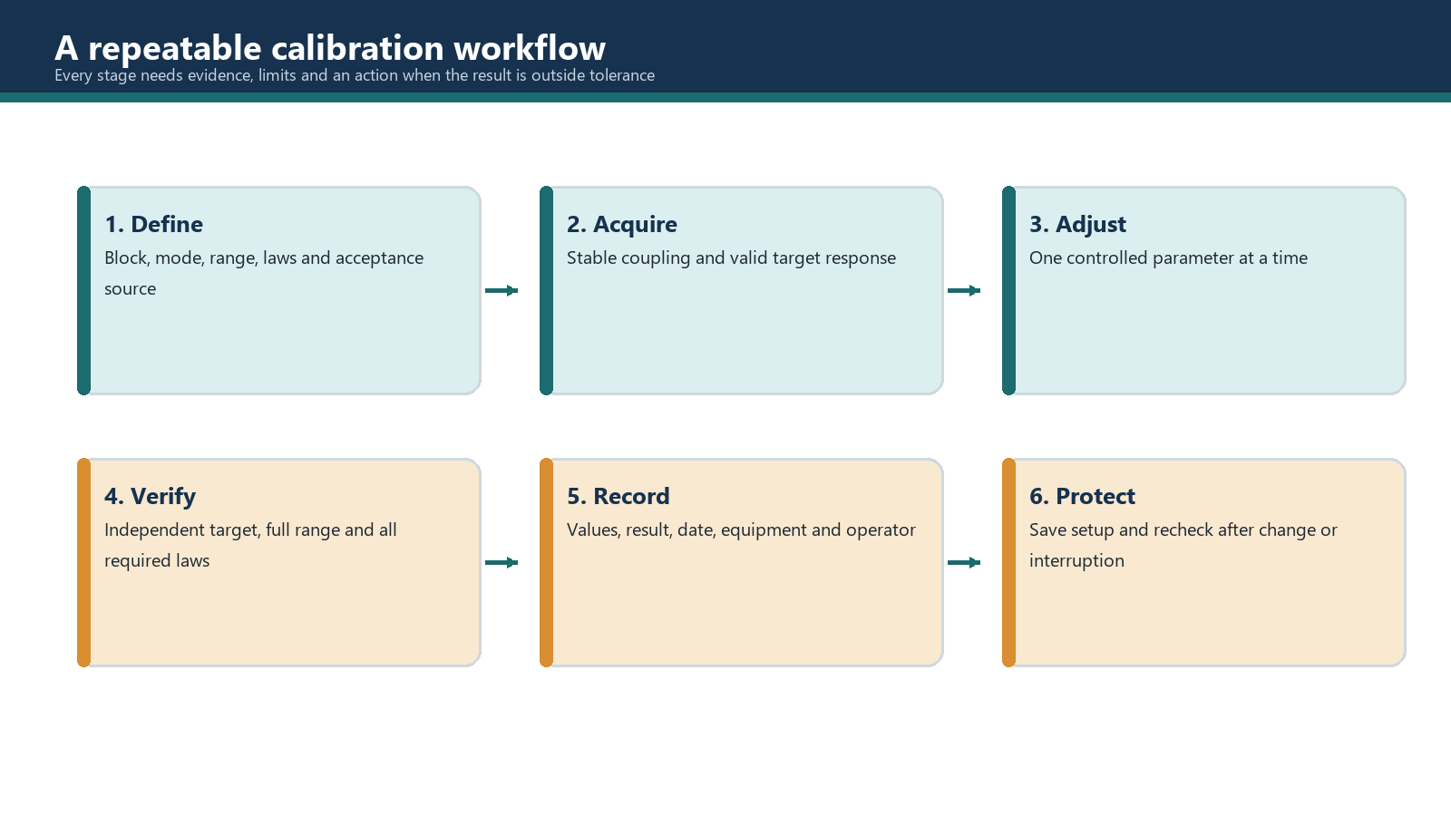
A defensible setup starts with identified equipment, verified inputs and an approved scan plan. Material velocity and wedge geometry influence focal laws; wedge delay corrects time/path offsets, sensitivity correction aligns reference response across laws, and DAC or TCG addresses response through distance. Each step needs verification and a controlled tolerance. Later corrections cannot rescue wrong geometry, velocity or coverage.
Study and revision only. This is not an approved inspection procedure, acceptance criterion or qualification.