
CHAPTER 6 · Phased Array Ultrasonics Level 2
Array Transducers and Wedges
In this chapter · 11 sections
Learning outcomes
After completing this chapter, the learner should be able to:
- describe the functional layers of a conventional or array transducer;
- distinguish single-element, dual-element and multi-element arrangements;
- explain how frequency, element size, element count and construction affect probe selection without treating any one value as decisive;
- compare linear, curved, dual-linear, matrix, circular and annular arrays;
- select a contact, delay-line, angle-beam or immersion arrangement for a stated inspection objective;
- identify wedge information that must be correct before focal laws are generated or calibration is accepted;
- recognise when a product-specific claim needs evidence rather than repetition.
Key terms
Active element: Piezoelectric material that converts electrical energy to mechanical vibration on transmission and mechanical vibration to electrical energy on reception.
Backing: Material behind the active element that controls ringing and absorbs energy travelling away from the test surface.
Matching layer: Layer used to improve transfer of acoustic energy between materials with different acoustic impedances.
Element count: The number of individually addressable or electrically grouped elements in an array. It is not the same as active aperture.
Linear array: Elements arranged in a line, normally allowing electronic control primarily in the plane along that line.
Matrix array: Elements arranged in two dimensions, allowing two-dimensional electronic control when the instrument and element connections support it.
Wedge: An acoustic delay and refracting component fitted between the probe and test surface.
Delay line: Material placed between the active element and the component to separate the initial pulse from early test responses or to protect the probe.
Index point: The defined reference position from which beam entry, probe position and scan offsets are related.
6.1 From a single crystal to an array
A conventional pulse-echo probe can use one active element for both transmission and reception. A dual-element probe separates those functions, using one element to transmit and another to receive. A phased array probe divides the active face into multiple elements that can be pulsed and received with controlled timing. The timing differences allow the system to form different beams from the same physical assembly.
The array does not remove normal UT requirements. Energy must cross the interfaces, enter in a useful mode, meet a favourably oriented reflector and return with adequate signal-to-noise ratio. More elements add control options and more opportunities for wrong probe data or failed channels.
Single-element probes remain useful where a fixed beam is adequate, access is simple and rapid setup is important. Dual-element probes can improve separation of interface and near-surface responses in some thickness or corrosion applications. Arrays are preferred when electronic steering, focusing, aperture movement, multi-angle coverage or encoded imaging provides a justified advantage.
6.2 Functional construction
Although designs vary, an ultrasonic transducer commonly contains the following functional layers:
- Active piezoelectric material: produces and receives vibration. Composite construction can tailor impedance and electromechanical behaviour.
- Electrodes and connections: carry excitation and return signals. Each array channel or group must be identified correctly.
- Backing or damping material: absorbs rearward energy and controls ring-down, pulse length and bandwidth.
- Matching and protective layers: improve acoustic transfer and protect the active face.
- Acoustic separation: kerfs or isolation material reduce unwanted mechanical coupling between neighbouring array elements.
- Housing, cable and connector: protect and connect the probe. Connector type alone does not state usable channels or transmit/receive arrangement.
- Wedge, delay line or water path: establishes the final acoustic interface and may refract, delay or shape the beam before it enters the component.
A suitable nominal frequency is of little value if the cable, channel map, wedge condition or programmed geometry is wrong.
6.3 Selection parameters
Frequency
Frequency influences wavelength, attenuation, scattering, beam dimensions and the response from small reflectors. Higher frequency can support finer spatial discrimination in suitable material, but attenuation and scattering normally increase. Lower frequency generally penetrates more difficult or longer paths, but may produce a wider beam and less separation of small or closely spaced responses.
The marked centre frequency is a nominal descriptor, not a promise that every transmitted pulse is a single pure frequency. The operating spectrum, damping, wedge, material, cable and receiver all affect the resulting signal.
Element count
Total element count describes how many elements are present. Active element count describes how many are used in one aperture or law. Neither value alone gives the aperture length. The physical aperture depends on element geometry and spacing, which are defined in Chapter 7.
A 64-element probe can use a 16-element active aperture, a different active count, or several groups, subject to the instrument and qualified setup. Saying that a probe has more elements does not automatically mean that every law uses a larger aperture, produces a narrower beam or has a longer near field.
Element dimensions and layout
Element width, pitch, kerf and passive-plane dimension influence directivity, aperture geometry and spatial sampling. Those quantities must not be exchanged casually. In particular, pitch is the centre-to-centre spacing; element width is the active width; kerf is the gap or isolation region between adjacent elements.
Sensitivity and usable range
Sensitivity depends on more than element area. Material attenuation, wedge loss, coupling, beam spread, focus, sound path, receiver noise and reflector orientation all contribute. Probe selection should therefore be supported by calculation, modelling where appropriate, reference-block response and practical performance evidence over the required range.
6.4 Common array arrangements
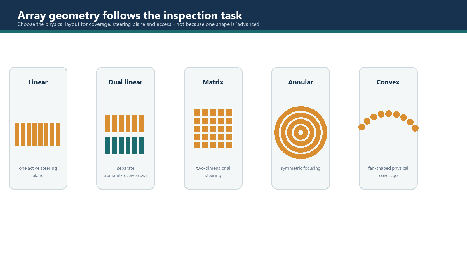
Linear array
A linear array places elements in one row. It is widely used for electronic aperture stepping, sectorial steering and active-plane focusing. The passive plane is normally governed by the fixed element elevation, lens or roof geometry rather than by independent electronic focusing.
Convex or concave array
A curved array can conform to a surface or alter the natural beam distribution. Its value depends on component curvature, access, coupling and the purpose of the inspection. A curved shape is not inherently superior; it is useful when the geometry solves a stated problem and the resulting laws can be verified.
Dual-linear array
A dual-linear array uses separate transmit and receive rows or groups. A roof angle may create an overlap region that helps some interface or near-surface applications, but that region changes with depth and geometry. Probe data and calibration must match the assembly.
Matrix and dual-matrix arrays
A matrix distributes elements in two dimensions and can control more than one plane when its channels and focal laws permit. It also increases law count, data volume, calibration and three-dimensional verification. Row-column or grouped designs may provide different control from a fully addressed matrix.
Circular and annular arrays
Circular arrangements place elements around an area or perimeter; annular arrays use concentric rings, commonly for axial focusing. Steering and scanning depend on the actual segmentation and channel arrangement.
6.5 Coupling arrangements
Direct contact places the probe or protective face against the coupled component. It is compact but may expose the probe to wear and can make very early responses difficult to separate.
Delay-line contact inserts a known material path between probe and component. The delay can separate the initial pulse from early component responses, protect the probe and adapt to a surface. Delay material, wear and temperature affect travel time.
Angle-beam contact uses a wedge to create a refracted mode and angle in the component. The wedge also moves the probe away from the beam entry point and introduces wedge echoes, attenuation and delay that must be controlled.
Immersion or water-column coupling uses a water path between probe and component. This supports repeatable scanning and non-contact beam entry but requires control of water path, alignment, bubbles, surface curvature, temperature and refraction.
The arrangement is selected by the inspection volume, expected reflector orientation, component geometry, surface condition, required resolution, coupling stability and practical access. It is not selected because a catalogue labels one probe as ideal.
6.6 Wedge information and verification
A wedge file or probe database entry is useful only when it describes the fitted hardware. Before focal laws are accepted, confirm at least:
- wedge identity and orientation;
- wedge material and the velocity value used at the relevant temperature;
- wedge angle, height and geometric reference dimensions;
- probe position and element orientation on the wedge;
- index-point and offset convention;
- roof angle or transmit/receive arrangement where applicable;
- component surface form, including flat or curved contact;
- intended wave mode and refracted-angle range;
- evidence that wear, machining or damage has not changed the geometry beyond the permitted condition.
Wedge delay calibration corrects a measured timing offset for the selected laws. It does not repair a wrong wedge velocity, incorrect geometric model or misidentified wedge. Calibration can make one displayed number agree while the beam quietly goes somewhere else, which is impressively unhelpful.
Worked example - selecting a probe arrangement
Scenario: A procedure-development exercise concerns a 20 mm thick, fine-grained carbon-steel butt weld. Both sides of the weld are accessible from the scanning surface. The principal targets are planar fusion-face discontinuities. The procedure permits shear-wave sectorial coverage, the surface is smooth, temperature is stable and a qualified angle-beam wedge family is available.
Assumptions: This is a training selection exercise, not a job instruction. Required angle range, sensitivity, acceptance criteria and calibration reflector are controlled elsewhere.
Reasoning:
- A linear array on an angle-beam wedge is a reasonable starting point for interrogating several fusion-face orientations.
- Select frequency from path, grain noise, target response and resolution; higher is not automatically better.
- Choose enough total elements for aperture movement, then define the active physical aperture separately.
- Verify angle range, mode, directivity, lobes, coverage and reference-target response. Weak near-surface coverage may require a different wedge, frequency, aperture, offset or supplementary scan rather than simply more elements.
Conclusion: The selection is a controlled combination of array, wedge, aperture and scan plan. The label on the probe is only the beginning of the evidence.
Common traps
- Treating total element count as active aperture. A probe may contain many elements while each law uses only part of the array.
- Using frequency as a quality ranking. Higher frequency may improve discrimination but lose usable penetration or signal-to-noise ratio.
- Assuming a matrix label guarantees two-plane control. Channel architecture and element addressing must support the claimed operation.
- Using a database entry without checking the hardware. Wedge identity, orientation, wear and probe mounting must match the file.
- Calling a probe type ideal without stated conditions. Suitability depends on the component, target, path, access and qualified performance.
- Expecting wedge-delay calibration to fix wrong geometry. It corrects timing offset, not an incorrect physical model.
Chapter summary
An array transducer is a layered electromechanical system whose performance depends on the active material, backing, matching layers, element isolation, wiring, housing and coupling arrangement. Single, dual and array probes each remain useful within an appropriate inspection problem.
Frequency, element count and array type are selection inputs, not stand-alone answers. Total element count is different from active element count and neither states the physical aperture without pitch and element width. Linear, curved, dual-linear, matrix, circular and annular arrays provide different forms of control and different verification burdens.
The wedge or delay path is part of the acoustic system. Its identity, velocity, temperature, geometry, orientation, index reference and physical condition must be correct before focal laws and calibration can be trusted.
Study and revision only. This is not an approved inspection procedure, acceptance criterion or qualification.