
CHAPTER 15 · Phased Array Ultrasonics Level 2
System Performance and Periodic Checks
In this chapter · 16 sections
Learning outcomes
After completing this chapter, the learner should be able to:
- create a check plan whose frequency and tolerances come from controlled requirements;
- distinguish initial performance qualification from routine stability checks;
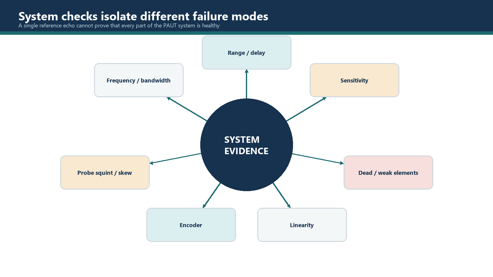
- check reference sensitivity, range, delay and encoder behaviour;
- identify dead, weak or misconnected array elements;
- evaluate probe squint or skew against a physical datum;
- explain vertical and horizontal linearity checks;
- calculate absolute and fractional bandwidth from defined FFT limits;
- respond correctly when a check fails; and
- record enough evidence to determine the validity of previously collected data.
Key terms
Baseline; periodic check; stability; tolerance source; drift; reference response; range; delay; encoder scale; polarity; squint; skew; dead element; weak element; channel order; vertical linearity; horizontal linearity; reserve gain; system gain; radio-frequency (RF) waveform; fast Fourier transform (FFT); centre frequency; peak frequency; bandwidth; fractional bandwidth; nonconformance.
15.1 A check plan, not a ritual
Performance checks show whether the system still behaves like the accepted baseline. Select them for relevant failure modes, not because another job used the same list.
The plan should state:
- what characteristic is checked;
- why that characteristic matters;
- the equipment and reference used;
- the method and settings;
- the expected observation;
- the tolerance and its controlled source;
- when the check is performed;
- who may perform and accept it;
- what happens if it fails; and
- how the result is recorded.
Check frequency comes from the standard, procedure, manufacturer, quality plan or client requirement. Checks may occur before use, at intervals, at collection boundaries, after changes or impact, after drift and following repair. No universal interval is invented here. A number without a controlled source is an opinion wearing a decimal point.
15.2 Baseline, routine check and requalification
An initial assessment establishes baselines such as element response, beam behaviour, linearity or frequency response. A routine check samples selected characteristics to detect change; it does not replace full qualification.
Failure, repair, substitution or significant change may trigger requalification. The plan distinguishes a repeated check, recalibration and broader reassessment.
15.3 Reference sensitivity, range and delay checks
Purpose
Confirm a known reflector remains at its expected amplitude and position.
Prerequisites
- the accepted setup or baseline;
- the same reference standard and target, or an approved equivalent;
- stable equipment temperature and coupling conditions;
- unchanged gain, pulser, receiver, filter, rectification, averaging and gate settings; and
- a recorded tolerance source.
Method
Maximise the target at the defined position and compare:
- amplitude with the baseline/reference level;
- indicated sound path or depth with the known value;
- the response across nominated laws or apertures; and
- any expected signal shape or location in the corrected view.
Identify coupling-transfer checks separately from instrument stability; do not change several variables and guess at the cause.
Acceptance evidence
Record expected/observed amplitude and position, limits and status. Evidence should show target, law, gate and settings.
Failure modes
- changed gain or filter;
- wrong law/group selected;
- wedge wear or temperature change;
- coupling variation;
- cable or connector fault;
- probe damage;
- incorrect target position; and
- instrument drift.
Records
Record target, setup/equipment, law, settings, baseline, observation, limit, result and action.
15.4 Encoder scale, direction and data continuity
Purpose
Confirm distance, direction and data continuity at representative movement speed.
Method
Move through a measured distance with representative contact and direction. Compare actual/displayed travel, return to datum where required, and verify polarity and axis. Inspect a representative scan for gaps, scale distortion, repeats and dropped acquisitions.
Acceptance evidence
Travel, direction and continuity must meet controlled limits. Verify every used axis and both directions where backlash/counting matters.
Failure modes
- wheel slip on couplant or scale;
- wrong wheel diameter/resolution;
- reversed polarity;
- scan and index encoders swapped;
- missed counts or loose couplings;
- backlash at direction reversal;
- lifting the encoder wheel; and
- scanning faster than the acquisition configuration permits.
Records
Record actual/displayed distance, axis, direction, resolution, conditions, speed, gaps and status.
15.5 Probe squint and skew
Squint is unwanted deviation of the beam from the intended plane. Skew can also be a deliberate setup coordinate, so the record must distinguish the programmed/physical skew from unintended beam deviation.
Purpose
Confirm beam direction relative to a physical datum.
Prerequisites
- a straight, known datum on the block or fixture;
- a suitable target whose response changes predictably with lateral rotation;
- verified probe orientation and element order;
- stable contact and coupling; and
- the check method and limit specified by the applicable procedure or manufacturer.
Method
Align to the datum, sweep rotation to find the target peak, and measure orientation or corrected target position. Repeat for reproducibility.
The target must suit the geometry; “use whichever block corner is nearby” is not a method. Cover enough laws to reveal meaningful misalignment.
Acceptance evidence
Record intended/measured direction or position, deviation, repeatability and limit.
Failure modes
- wedge wear or poor probe seating;
- probe/wedge misalignment;
- incorrect element orientation in the setup;
- lateral movement mistaken for rotation;
- an unsuitable or extended target; and
- accepting a noisy peak with poor repeatability.
Records
Record orientation, datum, target, laws, deviation, repeatability, limit and disposition.
15.6 Dead, weak and misconnected elements
An array can still form a plausible image with degraded elements while sensitivity, beam shape, steering or focus changes. Adjacent failures can be more serious because they create a larger inactive region.
Purpose
Compare element or small-aperture response and order with an accepted baseline.
Prerequisites
- an approved element-check routine or single-element/stepped-aperture configuration;
- a reference target that gives a stable response across the element positions;
- controlled gain, range, pulser and filter settings;
- consistent probe contact or an immersion/fixture arrangement; and
- acceptance criteria from the governing procedure, system qualification or manufacturer.
Method
Collect comparable responses by element number and look for:
- no transmit/receive response;
- a response materially lower than the baseline;
- excessive noise or intermittent behaviour;
- abrupt phase/time differences;
- channels appearing in the wrong order; and
- clusters of adjacent abnormal elements.
If true single-element operation is unavailable, use the approved diagnostic and understand its scope. Repeat suspicious results after restoring coupling/connectors, then substitute components systematically to isolate the cause.
Acceptance evidence
Retain an element-response plot/table, baseline, abnormalities and acceptance source. There is no universal dead-element allowance; effect depends on location, adjacency, apertures and laws.
Failure modes
- coupling variation across the probe face;
- a target too small or poorly aligned to illuminate all elements consistently;
- cable/adaptor damage mistaken for probe failure;
- applying automatic normalisation before reviewing raw element response;
- ignoring misordered channels because all channels show an echo; and
- masking a weak element with excessive gain.
Records
Record the equipment path, method, target, settings, element responses, disposition and substitutions.
15.7 Vertical linearity
Vertical linearity tests whether displayed amplitude follows controlled input/gain changes without clipping or compression.
Purpose
Confirm that indicated amplitude changes agree with controlled gain or attenuation changes over the range used for evaluation.
Prerequisites
- a stable, unsaturated echo;
- a calibrated gain or attenuator function as required by the check method;
- fixed pulser, filter, rectification, averaging and gate settings; and
- a defined set of amplitude or dB steps and acceptance limits.
Method
Set an unsaturated reference echo, apply the specified gain/attenuation steps and record amplitude. Avoid clipping and the noise floor. Approximately 6 dB doubles amplitude under the same impedance; power relationships differ.
Acceptance evidence
Tabulate expected versus observed amplitude and apply the controlled limit.
Failure modes
- beginning with a clipped echo;
- changing filters or rectification between points;
- using peak-hold data that does not reset;
- reading a gated measurement whose algorithm changes with signal shape; and
- confusing amplitude ratio with power ratio.
Records
Record target, channel/law, starting level, steps, observations, deviation and result.
15.8 Horizontal linearity and time-base accuracy
Horizontal linearity concerns the relationship between echo time/path and its displayed position across the examination range.
Purpose
Confirm that known intervals are represented consistently on the time base or sound-path scale.
Method
Use known reflectors or repeat echoes across the examination range. Compare every displayed position with its known value, distinguishing a common zero/delay shift from changing interval error.
Acceptance evidence
Record known/indicated positions, interval errors and the controlled limit.
Failure modes
- using a material velocity different from the known-path basis;
- confusing wedge-delay error with time-base nonlinearity;
- using echoes whose identities are uncertain;
- checking only a small part of a much larger examination range; and
- reading corrected depth while comparing with uncorrected sound path.
Records
Record range, delay, velocity/mode, targets, expected/observed positions, errors and result.
15.9 Overall response and reserve gain
Some techniques require proof that the complete system achieves reference response with adequate gain margin and usable SNR; terminology is defined by the controlling method.
Use the specified system and target, recording gain required, remaining margin or defined noise relationship. No universal reserve value applies, and gain cannot repair coverage or damage.
For target-to-noise checks, define the noise measurement, gate and RF/rectified mode. Explain every physical step rather than teaching it as ritual.
15.10 Centre frequency and bandwidth using FFT
An FFT converts a selected RF pulse into a spectrum representing the complete probe, path, cable, pulser, receiver, filter, sampling and target chain.
Purpose
Confirm that the system's spectral response is consistent with the approved baseline or specified performance range.
Prerequisites
- RF waveform acquisition with adequate sampling frequency;
- a stable target and repeatable coupling arrangement;
- the specified pulser, filter and receiver settings;
- a defined time window around the intended echo;
- the required spectral windowing method; and
- a specified amplitude drop level for determining frequency limits.
Method
- Acquire a clean, unsaturated RF echo from the nominated target.
- Set the time window so it contains the intended pulse without unrelated echoes.
- Apply the specified FFT and windowing method.
- Identify the peak frequency if the method requires it.
- Identify the lower frequency f_L and upper frequency f_H where the spectrum crosses the specified level below the reference peak.
- Calculate absolute bandwidth:
bandwidth = f_H - f_L
- If required, calculate fractional bandwidth:
fractional bandwidth (%) = [(f_H - f_L) / f_c] x 100
The method must define f_c. It may use a centre derived from the limit frequencies or another stated convention. Peak frequency and centre frequency are not automatically identical for an asymmetric spectrum.
Acceptance evidence
Save waveform, spectrum, settings, cursors, drop level, bandwidth and baseline comparison.
Failure modes
- using rectified rather than RF data;
- sampling too slowly for the highest frequency present;
- allowing an acquisition filter to define the apparent probe bandwidth without recording it;
- selecting a window containing more than one echo;
- measuring from a saturated waveform;
- calling (f_H + f_L)/2 the bandwidth; and
- assuming the spectral peak alone describes bandwidth.
Records
Record the equipment/path, target, acquisition and FFT settings, drop level, f_L, f_H, centre/peak convention, bandwidth and disposition.
15.11 Action on a failed check
A failed check creates a data-validity question. The correct response is controlled and traceable:
- stop using the affected setup;
- preserve the failed result and identify the time/data interval potentially affected;
- repeat the observation only after confirming the check was performed correctly;
- isolate the cause—settings, coupling, block, probe, wedge, cable, encoder, instrument or environment;
- correct or replace the affected item under the quality system;
- repeat the necessary calibration and performance checks;
- determine, with the authorised person, whether data collected since the last acceptable check remain valid or require re-examination;
- document the nonconformance, decision and corrective action; and
- release the system only after acceptable evidence is restored.
Do not adjust a setup until it passes and then erase the failed evidence. That destroys the information needed to decide whether earlier examination data were valid.
15.12 Minimum check record
A useful record includes:
- job/component and technique identification;
- date, time and examiner;
- instrument, software, probe, wedge, cable, scanner and encoder IDs;
- setup/group file identifier;
- reference block and target;
- environmental or temperature information where relevant;
- check method and settings;
- expected value and tolerance source;
- observed value and evidence file;
- pass/fail status;
- corrective action and repeated result; and
- disposition of data collected since the previous accepted check.
Common traps
- Performing a check because “we always do it” without knowing the failure it detects.
- Using a tolerance copied from a different procedure or instrument.
- Hiding weak elements with normalisation or gain.
- Checking encoder distance but not polarity or data gaps.
- Calling a wedge-delay shift horizontal nonlinearity.
- Calculating bandwidth as the mean of two frequencies.
- Treating spectral peak as centre frequency without defining the convention.
- Passing the equipment after repair without deciding what happens to earlier data.
Chapter summary
Periodic checks protect the link between an accepted setup and examination data. Each needs a purpose, method, evidence, controlled limit and response to failure. Checks cover elements, beam direction, amplitude/time-base linearity, encoder behaviour and spectral response; FFT bandwidth is f_H - f_L at a specified drop level. On failure, stop, preserve evidence, bound affected data, correct the cause and restore acceptance.
Study and revision only. This is not an approved inspection procedure, acceptance criterion or qualification.