
CHAPTER 25 · Ultrasonics Level 3
Sizing Evidence and the Integrity Handoff
In this chapter · 22 sections
Why this matters
A Level 2 technician can place cursors on two candidate responses and report a height to one decimal place. The Level 3 problem is deciding whether those responses really represent the upper and lower limits of one crack, how much bias and uncertainty remain, and which physical dimension the next engineering model needs. Ultrasonic Level 3 does not silently become fracture assessment. Its role is to provide bounded, traceable measurement evidence so the structural specialist can use the right dimension without guessing what the screen or report meant.
What you already need
- Pulse-echo and diffraction-based location and sizing concepts.
- The separation between indication, discontinuity and evaluation.
- Coordinate systems, beam-path assumptions and uncertainty layers.
- Detection and sizing reliability concepts from Chapter 23.
- Basic square roots and the use of supplied uncertainty components.
What you will learn
- Define crack tip, ligament, sizing bias and critical dimension plainly.
- Preserve competing interpretations until evidence resolves them.
- Separate measurement, model and association error in sizing.
- Explain how correlated tip errors affect a height difference.
- Translate ultrasonic coordinates into declared structural dimensions.
- Prepare an integrity-ready handoff without making an unauthorised structural decision.
Words you will meet
- Crack tip: local end or edge of a crack surface.
- Ligament: remaining material between a crack extremity and a reference boundary.
- Sizing bias: consistent difference between measured and reference dimension.
- Censoring: result limited by detection, resolution or reporting boundary rather than ordinary error.
- Association: decision that observations belong to the same physical feature.
- Structural assessment: engineering evaluation of flaw significance under load and material conditions.
- Critical dimension: crack dimension associated with a stated structural limit or action.
- Stress intensity: fracture-mechanics quantity describing crack-tip loading under a defined model.
- Guard band: measurement decision boundary displaced to manage stated decision risk.
- Integrity handoff: traceable transfer of inspection evidence into structural assessment.
Depth guide for this chapter
- Understand here: signal identity, error layers, dimension definitions and the inspection-to-integrity boundary.
- Calculate here: simple resolution checks, covariance-aware height uncertainty and sensitivity of a supplied fracture expression.
- Derive later: covariance matrices and decision uncertainty are developed in Chapters 64 and 78. Fracture-solution derivation remains the structural specialist’s discipline.
25.1 Start with the physical words
A crack tip is a local end of the crack surface; in a through-wall cross-section, technicians often refer to an upper and lower tip. A rough or branched crack can have several local edges rather than two ideal points. A diffracted ultrasonic response may arise near an edge, but the response must still be identified as belonging to that edge. The ligament is remaining material between a crack extremity and a defined boundary; it may mean remaining wall to the far surface or another structural boundary. It is not interchangeable with crack height. If wall thickness is 20 mm and the deepest crack tip is 14 mm from the entry surface, the remaining far-surface ligament is 6 mm under that coordinate model.
Sizing bias is a consistent tendency for measured size to differ from reference truth; positive height bias means the method tends to report larger heights. Bias may depend on size, depth, target type and orientation. One average correction is safe only inside the domain that established it. A structural assessment combines flaw geometry with stress, material resistance, component geometry and other assumptions; a critical dimension is a dimension associated with a particular assessment limit or action. It is not an ultrasonic calibration reflector or a universal reject size.
These definitions establish the boundary; ultrasonics measures or infers physical evidence. Structural assessment decides significance through its own controlled model. The two disciplines must exchange precisely defined quantities.
25.2 Preserve hypotheses before selecting a size
An advanced interpretation links each observation to a physical hypothesis; a response may be a face reflection, upper tip, lower tip, corner trap, component geometry, mode conversion or structural noise. Multi-view displays add value only when the contributing paths and evidence are understood. A useful interpretation record can list candidate causes against observations such as arrival time, movement with probe position, angle response, phase or polarity where applicable, spectrum, opposite-side response and coordinate agreement; no single observation proves identity. A pattern of independent evidence can increase or reduce support.
Strong early labels create anchoring; a response at the calculated root path can remain compatible with root geometry or a planar reflector near the root. Directional peaking aligned with a fusion face supports the planar hypothesis. Reproduction at exact root coordinates from physically different paths may support geometry. The conclusion should preserve alternatives when the evidence remains divided. Evidence independence matters; several reconstructed views using the same aperture and samples are correlated. Their visual agreement is not equal to agreement from an opposite-side path or another physical mode. A weaker independent view can be more informative than several brighter versions of the same interaction.
25.3 Tip identity and resolution
A tip response is commonly weaker and less specular than a face reflection; an upper tip can be hidden in entry-surface dead zone. A lower tip can merge with a back-wall, corner or lateral-wave feature. Branching and roughness create several candidate edges. Tip identity is supported by movement, arrival order, phase or polarity when validated, convergence across views and compatibility with a physical crack model; two cursor positions are not automatically two tips. The record should state which physical points they are believed to represent.
Resolution places a lower bound on separable arrivals; when two responses overlap within the complete-system pulse, their combined peak moves with relative amplitude and phase. Fitting algorithms may estimate closer components under a declared signal model, but uncertainty rises quickly when the model or component count is wrong.
| Worked example · Testing whether two arrivals are directly resolvable WE-25-03 Given: The measured -6 dB envelope duration corresponds to 1.8 mm pulse-echo depth. Candidate tip depths are 14.0 mm and 15.2 mm, separated by 1.2 mm. Independent views do not isolate the peaks. Find: Whether ordinary pulse separation directly supports the two-cursor height. Steps: Compare the 1.2 mm candidate separation with the 1.8 mm measured response duration. The separation is smaller than the response scale. Answer: The two ordinary envelope peaks are not directly resolved under this criterion. Technical implication: A 1.2 mm cursor separation is an algorithmic or interpretive estimate rather than demonstrated independent-tip measurement. Additional evidence or a censored result is more defensible. Common mistake: Extra decimal places from curve fitting do not restore information absent from the measured waveform. |
|---|
Censoring should remain in the dataset; a result such as “tips not resolved below 1.8 mm” is not an ordinary zero-height measurement. Discarding failed-to-size cases makes a technique appear more accurate than it is.
25.4 Three layers of sizing error
Sizing error can be organised into three layers. Measurement error includes timing, position, angle, velocity and cursor variation under one model. Model error includes an incorrect path, beam direction, response model or diffraction assumption. Association error occurs when a real signal is assigned to the wrong feature or when responses from separate features are combined.
Continuous uncertainty propagation can support the first layer when the model is locally stable; alternative models are more appropriate for the second. Coordinate registration and spatial association rules address the third. Combining all three into one normal distribution can hide a small but important probability of wrong-tip selection. Outliers therefore deserve physical review; a technique may show low spread on most specimens and occasional large undersizing when the wrong upper response is chosen. Its mean and standard deviation can look acceptable while the lower tail remains hazardous. Reliability evidence should retain these cases and state failure-to-size rates when data support them.
Metrology guidance provides a disciplined vocabulary for quantified components and covariance. [R031] [R032] Categorical model and association uncertainty still need explicit alternatives rather than forced numeric neatness.
25.5 Shared errors can cancel in a difference
Height calculated from upper and lower tip depths is a difference; a shared velocity error can move both depths in the same direction and partly cancel. Independent picking errors combine. Covariance records this shared movement.
| (25.1) Uncertainty of a difference with covariance · EQ-25-02 Where: u_h = standard uncertainty of height difference; u_upper and u_lower = standard uncertainties of tip depths; cov = covariance in squared length units Model limits: linear difference model and covariance estimated consistently |
|---|
The observable is standard uncertainty of a height difference under a stated tip and path model; positive covariance reduces difference uncertainty because the two coordinates move together. Different paths or directional velocity can reduce that cancellation.
| Worked example · Combining correlated tip-location errors WE-25-02 Given: Upper and lower tip depths each have 0.8 mm standard uncertainty. A common velocity component is 0.6 mm for each. The remaining independent picking component is sqrt(0.8^2 - 0.6^2) = 0.529 mm. Find: Standard uncertainty in the height difference when the common component is perfectly correlated and equal. Steps: The common velocity shift cancels in subtraction. Combine independent pick components: sqrt(0.529^2 + 0.529^2) = 0.748 mm. Answer: Height standard uncertainty is approximately 0.75 mm. Technical implication: Treating full depth uncertainties as independent would give 1.13 mm and overstate this particular difference uncertainty. Unequal paths would need a different covariance model. Common mistake: Assuming either complete independence or complete cancellation without examining shared physical inputs can bias the uncertainty in either direction. |
|---|
At Level 3, supplied components and a simple covariance model can be used; matrix derivation, nonlinear propagation and Monte Carlo alternatives continue in Chapter 64.8, Chapter 64.12 and Chapter 78.3.
25.6 Bias correction and its boundary
A stable bias can sometimes be corrected; the correction has uncertainty from finite calibration data, target truth and future drift. It applies only across the demonstrated size, material, geometry, signal and operator domain. Suppose a threshold-based method overestimates height by 1.0 mm on average. Subtracting 1.0 mm can centre the tested sample. It does not reduce random spread or wrong-tip events. It may worsen small results if resolution already forces a minimum reported height.
Cross-validation protects against optimistic correction; a relationship fitted and tested on the same small set will look better than it transfers. Withheld or independent specimens provide stronger evidence. The purpose of correction is a better measurement, not a faultlessly straight development plot. Sizing performance should show residual distribution, dependence on true size, outliers, censored outcomes and uncertainty coverage; detection capability remains separate because a method can be unbiased only for the subset of flaws it successfully detects and sizes.
25.7 The structural connection in plain language
Structural significance depends on applied stress, component geometry, material resistance and flaw geometry. Linear-elastic fracture mechanics often uses a Mode I stress-intensity form:
| (25.2) Illustrative Mode I stress-intensity form · EQ-25-01 Where: K_I = Mode I stress-intensity factor (Pa sqrt(m)); Y = dimensionless geometry factor; sigma = applied nominal stress (Pa); a = crack dimension defined by the selected solution (m) Model limits: linear-elastic fracture mechanics, appropriate geometry solution and Mode I representation; not an acceptance formula |
|---|
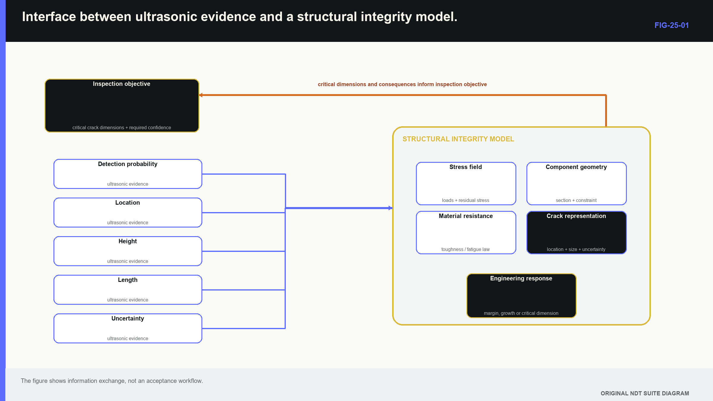
This equation is included to show the interface, not to turn ultrasonic Level 3 into a fracture analyst; the structural specialist selects the correct crack definition, geometry factor, stress and material model. The ultrasonic handoff must supply the dimension represented by a, its coordinates, uncertainty and model limits. The figure below shows information moving in both directions; structural needs define which dimensions matter. Ultrasonic capability determines how strongly those dimensions are supported.
| Worked example · Showing crack-size sensitivity in a supplied fracture expression WE-25-01 Given: Use the illustrative equation with constant Y and stress. Estimated a = 6.0 mm has an expanded interval from 4.5 mm to 7.5 mm. Find: Ratio of stress intensity at each interval bound to the value at 6.0 mm. Steps: With all other terms constant, ratio is sqrt(a_bound/a_est). Lower ratio is sqrt(4.5/6.0) = 0.866. Upper ratio is sqrt(7.5/6.0) = 1.118. Answer: The size interval maps to approximately -13.4% to +11.8% variation in calculated K_I under this simplified model. Technical implication: Inspection uncertainty can materially affect the structural input, but acceptability depends on the complete authorised assessment. Common mistake: Treating this sensitivity calculation as a fracture-acceptance decision ignores stress, resistance, geometry validity and governing requirements. |
|---|
The square-root relationship means size and stress intensity do not change one-for-one; it also shows why the exact definition of a matters. Through-wall height, depth, half-length and surface length can enter different structural solutions.
25.8 Inspection capability and critical dimensions
A structural assessment may identify a critical or tolerable dimension under stated loads and material properties; inspection capability should be compared with the relevant flaw population, not only with the numerical critical value. Detection reliability must cover the structurally important size and orientation range; mean sizing bias must be considered with spread, outliers and under-sizing tail. A mean error smaller than the critical dimension is weak evidence if the system occasionally misses or substantially under-sizes unfavourably oriented targets.
NASA reliability guidance treats POD as a property of a defined inspection system and population. [R034] That principle remains important at the integrity interface; a sizing method can be accurate conditional on detection while the detection system misses some critical orientations. A guard band can move a measurement action threshold away from an engineering limit to manage a stated risk; its size should follow supported uncertainty and decision consequence. A numeric guard band cannot repair unresolved model identity. Another view, method or characterisation is preferable when the reported feature itself remains uncertain.
The word conservative also needs direction; overestimating crack height may reduce one false-negative risk while driving unnecessary intervention. Underestimating remaining wall may be conservative in one model, while the same numerical bias applied to crack depth may not be. The downstream model and consequence must be named.
25.9 Reconciling different methods
Methods often measure different physical features; pulse-echo amplitude can follow an illuminated face. Diffraction timing can follow extremities. Radiography can show projected density changes. Surface examination can show surface-breaking length. Their numbers cannot be ranked until coordinates and dimension definitions align. Registration includes datum location, scanner position, component movement and surface geometry; if two indication centres differ by less than combined registration uncertainty, declaring them separate may be unsupported. A larger disagreement still needs review of response location and model bias.
| Worked example · Testing coordinate agreement between two methods WE-25-04 Given: Method A locates a feature centre at 126.0 mm with 1.5 mm standard uncertainty. Method B locates it at 130.0 mm with 2.0 mm standard uncertainty. Treat the errors as independent. Find: The coordinate difference relative to combined standard uncertainty. Steps: Difference is 4.0 mm. Combined standard uncertainty is sqrt(1.5^2 + 2.0^2) = 2.5 mm. Normalised difference is 4.0/2.5 = 1.6. Answer: The centres differ by 1.6 combined standard uncertainties. Technical implication: The result shows tension but does not prove two separate features. Registration bias and the physical response locations need review. Common mistake: Forcing the coordinates to agree or declaring separate flaws solely from this number skips the association model. |
|---|
Contradiction can be localised; two methods can agree on presence and depth while differing on length. A combined evidence table should preserve agreement and conflict for each quantity. The final physical model can remain an interval or set of alternative geometries.
25.10 Technical decision case: a traceable integrity handoff
Consider a fusion-face indication detected from two pulse-echo directions; a strong face response suggests a 24 mm illuminated length. Two weaker candidate extremity signals suggest 5.8 mm height, but one signal overlaps root geometry. A complementary diffraction view supports a lower extremity and gives a 17 mm interval between stable end responses. Component registration between datasets has 2.0 mm expanded uncertainty. The Level 3 analyst builds a hypothesis network rather than selecting the largest dimension; evidence supports a planar crack-like feature near the fusion face. Face-response extent and extremity interval represent different physical quantities. Height has two plausible values depending on upper-tip identity. The report retains both candidate tip coordinates, the root-geometry conflict, the method-specific lengths and the registration uncertainty.
The structural assessor identifies the required inputs: crack depth, through-wall height, surface or embedded status, half-length and orientation; the ultrasonic record maps observed coordinates into those definitions only where supported. It does not label the feature surface breaking without evidence. It does not choose a fracture geometry factor. It supplies detection capability, sizing method, correction, uncertainty and unresolved alternatives. The next figure shows this coordinate transformation; notice that measurement, model and association uncertainty enter before the structural model.
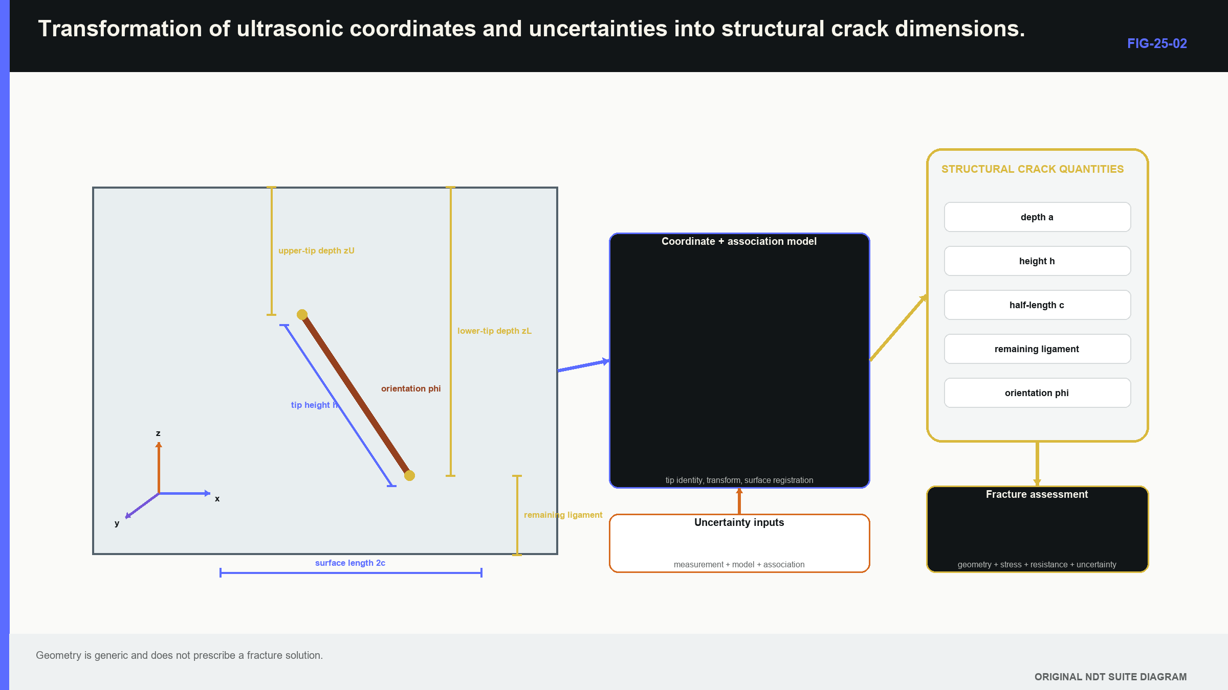
The integrity-ready output includes:
- Component datum, axes, surfaces and coordinate units.
- Physical feature and association hypothesis.
- Measured and inferred coordinates with dimension definitions.
- Observed response mechanisms and supporting views.
- Sizing method, bias correction and uncertainty.
- Detection and sizing capability domain.
- Censored values, alternatives and unsupported assumptions.
- Raw-data and reproducible-analysis identity.
This structure lets another specialist use the evidence without reverse-engineering the screen; a later structural question may require a dimension not prominent in the original report. Retained coordinates and raw evidence support reanalysis, whereas one flattened image and “size 6 mm” do not.
25.11 Formal depth and the Part VIII handoff
Part III expects the learner to recognise response identity, use supplied covariance and explain the boundary to structural assessment. Further mathematical treatment is staged as follows:
- Chapter 64.8 develops covariance and dependence.
- Chapter 64.12 develops propagation through coordinate models.
- Chapter 78.3 develops nonlinear uncertainty propagation.
- Chapters 78.8, 78.9 and 78.14 develop decision consequence, capability and guard-band logic.
- Chapter 78.21 separates indication, measurement and decision.
Derivation and approval of fracture-mechanics solutions remain outside the ultrasonic Level 3 role unless the individual separately holds that competence and authority; the handoff is successful when the assessment model receives the right quantity and its evidence boundary.
In plain words
- A cursor response must be identified physically before it becomes a crack tip.
- Crack height, crack depth, length and remaining ligament are different dimensions.
- Failed or unresolved sizing results must remain visible rather than being discarded.
- Measurement, model and association errors need different controls.
- Shared errors can cancel partly when two coordinates are subtracted.
- Bias correction carries uncertainty and applies only inside its demonstrated domain.
- Ultrasonic Level 3 supplies bounded evidence rather than silently performing structural assessment.
- An integrity-ready handoff preserves coordinates, definitions, alternatives and provenance.
Key terms
- Crack tip: local end of a crack surface.
- Ligament: remaining material to a declared boundary.
- Sizing bias: consistent measured-to-reference difference.
- Censoring: limitation created by measurement or reporting boundary.
- Association: decision that observations belong to one feature.
- Structural assessment: model-based evaluation of flaw significance.
- Critical dimension: dimension associated with a stated structural boundary.
- Guard band: shifted measurement threshold used to control decision risk.
Key relationships
- u_h^2 = u_upper^2 + u_lower^2 - 2 cov: shared coordinate errors affect height uncertainty through covariance.
- K_I = Y sigma sqrt(pi a): illustrative structural sensitivity requires a defined crack dimension and authorised model.
- ultrasonic coordinates -> declared crack dimensions -> structural model: the handoff needs explicit transformations and uncertainty.
Common mix-ups
- Two cursor peaks are not automatically two crack tips.
- A precise number is not necessarily a resolved measurement.
- Detection reliability is not sizing reliability.
- The largest method result is not automatically the conservative result.
- A structural critical size is not an ultrasonic calibration value.
Bridge to Chapter 26
Chapter 25 showed how a technical result moves into another engineering decision without losing its assumptions; chapter 26 applies the same traceability to standards, contracts, procedures, data and change. It begins with the practical conflict between several documents and separates the authority question from the physics question.
Sources and further study
- [R031]
- [R032]
- [R034]
Study and revision only. This is not an approved inspection procedure, acceptance criterion or qualification.