
CHAPTER 7 · Phased Array Ultrasonics Level 2
Array Geometry and Electronic Beam Steering
In this chapter · 13 sections
Learning outcomes
After completing this chapter, the learner should be able to:
- define element width, pitch, kerf and the active and passive array directions;
- calculate a physical array or active-aperture length from declared geometry;
- distinguish element count from physical, active and effective aperture;
- explain beam formation using wavelet interference and controlled delay;
- distinguish individual-element directivity from the beam formed by the complete aperture;
- explain why steering capability is limited by the whole probe-wedge-material system;
- reject the claim that a useful refracted bulk wave can simply be steered beyond 90 degrees;
- identify the evidence needed to qualify a proposed steering range.
Key terms
Element width, e: Active dimension of one element in the array direction under discussion.
Pitch, p: Centre-to-centre distance between adjacent elements.
Kerf, g: Separation between adjacent active elements. In a simple uniform array, it is the difference between pitch and element width.
Active plane: Plane along the element row in which a one-dimensional linear array normally performs electronic steering or aperture movement.
Passive plane: Plane perpendicular to the active plane. Its beam behaviour is commonly set by element elevation and fixed acoustic geometry in a one-dimensional array.
Active aperture: The set of elements used by a focal law and the physical dimension spanned by those elements.
Effective aperture: The portion or projection of an aperture that contributes to beam formation in the declared propagation geometry.
Directivity: Variation of an element's or aperture's radiated response with direction.
Steering angle: Direction of the formed beam using a stated angular convention, medium and wave mode.
7.1 Geometry starts with definitions
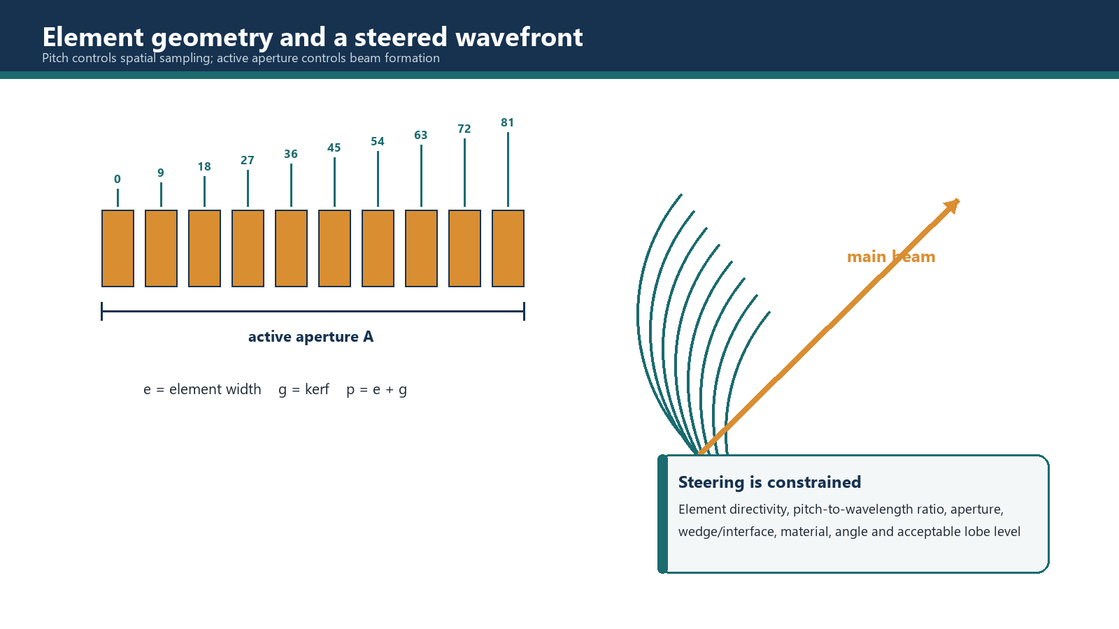
Array terminology must be fixed before any beam calculation. For a uniform linear array, pitch is measured from the centre of one element to the centre of the next. Element width is the active width of one element. Kerf is the intervening gap or isolation region. These values may be close, but they are not interchangeable.
The distinction matters for two different reasons. Element width influences the natural directional response of each element. Pitch controls how the array samples the wavefront spatially and is therefore central to grating-lobe behaviour. The total or active physical length depends on both pitch and element width.
Manufacturers may use different axis names, especially for matrix or curved arrays. The technique record should therefore include a labelled sketch showing element numbering, active direction, passive direction, cable exit, wedge orientation, scan axis and index reference. A symbol without a direction is an invitation to configure the correct value on the wrong axis.
7.2 Physical, active and effective aperture
The physical length across a uniform row is not simply the element count multiplied by pitch. A row of n elements contains n - 1 centre-to-centre pitch intervals, plus one element width across the two outer half-elements.
A = (N - 1)p + e
This physical relation should be the primary aperture calculation for a uniform array. Multiplying count by pitch is an approximation that silently treats the end geometry differently. The error may be small in one example and material in another; either way, the convention must be stated.
Total physical aperture spans the complete connected row or declared array dimension.
Active aperture spans only the elements used for a particular law. A 64-element array with 16 active elements has a 16-element active aperture, not a 64-element active aperture.
Passive aperture refers to the aperture dimension in the non-electronically controlled plane for the context being discussed. For a simple linear array, this is often close to the element elevation, but lenses, roofs, segmentation and curvature can change the effective behaviour.
Effective aperture accounts for the way the aperture is presented to the beam direction and interface geometry. A projected-aperture relation must define the incident and refracted angles, surfaces and sign convention before it is used.
A_effective = projected active aperture in the declared propagation plane
Element count alone cannot establish beam width, near-field length or focal capability. If active count rises while pitch and element width stay fixed, the active physical aperture rises. If the same count is retained and only element segmentation changes, the result may be different. Always follow the dimension, not the marketing integer.
7.3 How an aperture forms a beam
Each active element produces a wavelet. Where wavelets arrive in phase, their pressure contributions reinforce; where they arrive out of phase, they partly cancel. The combined field contains a main lobe and smaller off-axis features whose position and amplitude depend on aperture geometry, wavelength, timing and amplitude weighting.
With equal timing, a straight array in a uniform medium forms a beam around its natural normal direction. Applying a progressive delay across the elements tilts the direction in which the wavelets reinforce. Applying a curved delay pattern can make them reinforce around a selected focal region. Combining the two patterns allows steering and focusing together.
The focal law is therefore more than a list of angles. It contains transmit and receive timing associated with a declared probe, wedge, material, wave mode and geometry. Change one of those inputs and the calculated alignment changes.
7.4 Transmit and receive timing
On transmission, elements are pulsed at different times so that their wavelets reach the intended wavefront or focal region together. On reception, signals arriving at different elements are delayed before summation so that energy from the selected direction and depth adds coherently.
Transmit focusing is fixed by the delays used for that transmitted pulse. Receive focusing can be fixed or changed with time after the pulse, producing dynamic receive focusing as discussed in Chapter 8. Receive delay is not merely the transmit sequence played backwards: it is calculated for the returning paths and the selected receive strategy.
The sign of a delay slope depends on element numbering and the angular convention. Do not memorise a fixed rule such as "left elements first" without a labelled diagram. The correct first element changes when the probe, wedge or scan direction is reversed.
7.5 Element directivity is not total-aperture divergence
Two related effects are often confused.
An individual element has a natural angular response. For a fixed wavelength, a smaller element width generally produces a broader element directivity pattern. This broader element response can support useful steering over a wider angular region, provided pitch and the rest of the system remain suitable.
The formed aperture has a main beam whose width depends on effective aperture, wavelength, path and focus. For a fixed wavelength and comparable conditions, a larger effective aperture generally narrows the main beam. A smaller aperture generally broadens it.
There is no contradiction: small individual elements can radiate broadly, while many of those elements acting over a large aperture can interfere to form a narrow steered beam. Element directivity and formed-aperture beam width are different scales and must remain separate when element size, steering and beam width are compared.
7.6 What limits steering
Steering capability is not a universal plus-or-minus angle attached to every phased array. It is limited by the complete acoustic and electronic system, including:
- element directivity at the operating spectrum;
- pitch relative to wavelength;
- active and effective aperture;
- wedge angle, wedge mode and interface refraction;
- critical-angle and mode-conversion behaviour;
- grating and side lobes;
- material attenuation, anisotropy and scattering;
- sound path, focus and signal-to-noise ratio;
- instrument channel capability and focal-law implementation;
- physical access and the qualified scan plan.
Angles must state their reference. If refracted angle is measured from the normal in the test material, 0 degrees is normal entry and 90 degrees lies along the surface. A claim of a propagating refracted bulk-wave beam "beyond 90 degrees" is not a useful extension of the sector; it points the mathematical direction back toward the interface rather than deeper into the component. Practical modes near the interface, surface waves and mode-converted waves require their own definitions and are not evidence of ordinary bulk-wave steering past 90 degrees.
As steering moves away from the natural direction, sensitivity can fall, the effective aperture and beam shape can change, and unwanted lobes can become more significant. The usable range must be established by modelling or calculation supported by representative reference-block measurements and the governing procedure.
7.7 Beam spread and coverage
Beam spread is not automatically bad. A broad beam may improve general insonification but reduce lateral discrimination and location precision. A narrow focused beam can improve response and discrimination near the focal region but may leave less tolerance for misalignment and may not remain narrow over the full depth range.
Coverage planning must use the characterised beam, not just the central ray. A scan plan should show the relevant beam boundaries or validated sensitivity region, the component volume and the expected reflector orientations. Central rays can demonstrate geometry; they do not prove that sensitivity is adequate throughout the claimed coverage.
Worked example 1 - calculating physical aperture
Given: A uniform linear array has element width e = 0.50 mm and pitch p = 0.60 mm. A focal law uses 16 adjacent elements. The full probe has 64 elements.
Assumptions: Elements are uniformly spaced in one straight row; the stated width is the active-plane width; no missing element lies inside the aperture.
Active aperture: Sixteen elements span fifteen pitch intervals plus one element width. The physical active length is therefore 15 x 0.60 + 0.50 = 9.50 mm.
Total aperture: Sixty-four elements span sixty-three pitch intervals plus one element width. The total physical length is 63 x 0.60 + 0.50 = 38.30 mm.
Comparison: The approximation n x p would give 9.60 mm and 38.40 mm. The difference is small here, but the exact geometry is known, so there is no benefit in throwing part of it away.
Worked example 2 - why count is not aperture
Probe A: 16 active elements, p = 0.60 mm, e = 0.50 mm -> active length 9.50 mm.
Probe B: 16 active elements, p = 0.80 mm, e = 0.65 mm -> active length 15 x 0.80 + 0.65 = 12.65 mm.
Assumptions: Both are uniform linear arrays used at the same nominal frequency in the same material. No claim is made that either probe is acceptable for a particular steering range.
Result: Both laws use 16 elements, but Probe B has an active physical aperture 3.15 mm longer. It may form a narrower main beam under comparable conditions, yet its larger pitch also changes spatial-sampling and grating-lobe risk. A higher element count or longer aperture is not automatically the better technique; the complete behaviour must be checked.
Common traps
- Using pitch and element width as synonyms. Pitch is centre spacing; element width is active material width.
- Calculating aperture as element count alone. Aperture is a length derived from geometry.
- Assuming more elements always narrow the beam. The active physical aperture must actually increase under comparable conditions.
- Using element directivity as the formed-beam width. One describes a single element; the other describes interference across the aperture.
- Quoting a universal steering range. Useful limits depend on the complete probe-wedge-material and procedure combination.
- Accepting angles beyond 90 degrees as deeper bulk-wave steering. The convention and propagating mode have been misunderstood.
- Proving coverage with central rays only. Sensitivity and characterised beam dimensions are also required.
Chapter summary
Element width, pitch and kerf describe different parts of array geometry. Pitch controls centre spacing and spatial sampling; width influences element directivity; kerf separates elements. Physical aperture is calculated from the number of pitch intervals plus one element width. Total element count, active element count and effective aperture must remain distinct.
Beam steering and focusing arise from constructive and destructive interference produced by controlled transmit and receive delays. Small individual elements can have broad directivity while a large active aperture forms a narrow main beam. Steering is limited by directivity, pitch/wavelength ratio, aperture, wedge and interface behaviour, lobes, material response and signal quality. A usable refracted bulk-wave sector is not extended by claiming angles beyond 90 degrees.
Study and revision only. This is not an approved inspection procedure, acceptance criterion or qualification.