
CHAPTER 2 · Phased Array Ultrasonics Level 2
From Pulse-Echo UT to Phased Arrays
In this chapter · 10 sections
Learning outcomes
After completing this chapter, the learner should be able to:
- outline the main stages in the development of industrial ultrasonic testing;
- describe the basic pulse-echo information carried by time and amplitude;
- explain how an array transducer differs from a conventional single-element probe;
- explain how controlled time delays allow electronic steering, focusing and scanning;
- identify the principal operational benefits and added controls of PAUT;
- distinguish the features that PAUT changes from the ultrasonic principles that remain unchanged.
Key terms
Pulse-echo: A technique in which a transducer sends an ultrasonic pulse and receives echoes returning from interfaces or reflectors.
Piezoelectric element: Material that converts electrical energy to mechanical vibration and converts returning mechanical vibration to an electrical signal.
Array: A set of individually connected transducer elements arranged within one probe housing.
Phasing: Applying controlled timing differences between element signals so their wave components combine in a selected way.
Focal law: The programmed transmit and receive delays used to form a beam with a chosen angle, position or focus.
Electronic steering: Changing beam direction by changing element timing rather than rotating the probe to each angle.
Electronic scanning: Moving the effective beam or active aperture through the array without moving the whole probe in that direction.
2.1 Begin with what PAUT changes
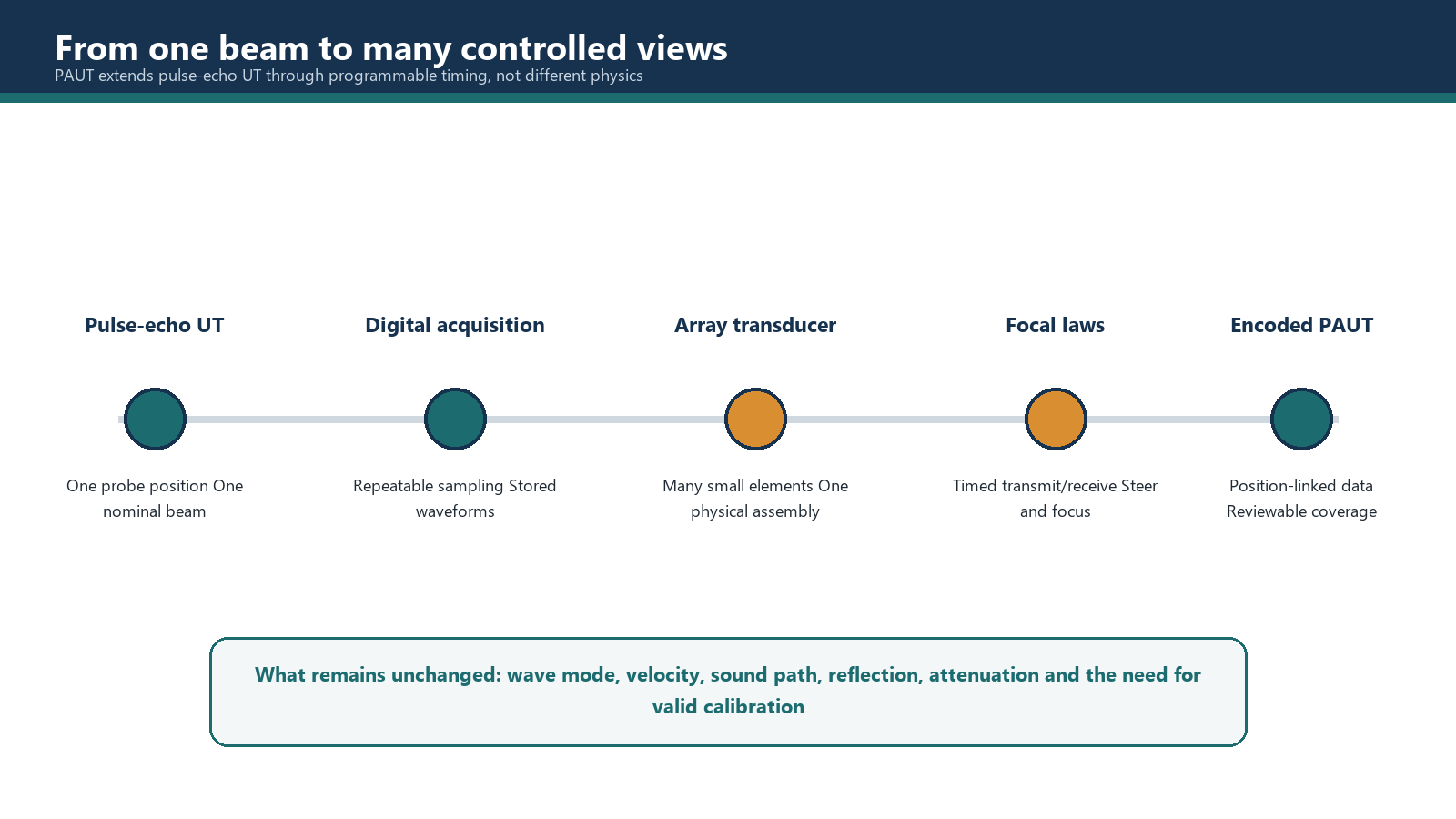
The easiest way to understand phased array is to compare it with the familiar pulse-echo process.
A conventional probe contains an active element that is excited electrically. The element vibrates and launches an ultrasonic pulse. The pulse travels through the test material and interacts with boundaries, geometry and discontinuities. A returning echo vibrates the element and is converted back into an electrical signal. The instrument displays the signal in relation to time and amplitude.
Time, together with the relevant sound velocity and beam path, helps establish where a response occurred. Amplitude shows the strength of the received response under the current setup. Neither value independently identifies a flaw. Position, orientation, material response, beam characteristics, coupling and calibration all influence what appears on the screen.
A phased array probe divides the active material into many separately connected elements. The instrument can excite selected elements at slightly different times and apply corresponding delays when receiving. When the timing is correct, the separate wave components combine to form a useful wavefront. Changing the timing pattern changes the beam.
From one probe position, the system may therefore create:
- a beam at a selected refracted angle;
- a set of beams covering a range of angles;
- a focused beam at a selected depth or sound path;
- a beam moved across the length of an array by stepping the active elements;
- more than one programmed beam group for different inspection needs.
The timing pattern used to create and receive one beam is a focal law. PAUT images are assembled from the A-scan information produced by those laws. The image is not a photograph of the component. It is a structured display of ultrasonic responses, which still requires interpretation.
2.2 How industrial ultrasonic testing reached PAUT
The development of PAUT was not a single invention. It resulted from improvements in sound generation, electronics, computing and data handling.
Early industrial ultrasound
During the early twentieth century, researchers began applying high-frequency sound to the detection of internal material conditions. Sokolov's work in 1929 was an important early investigation into ultrasonic flaw detection in metals. The practical idea was already recognisable: introduce sound into a material and use its interaction with internal features to reveal hidden conditions.
Practical pulse-echo equipment
Demand for reliable inspection increased sharply during the Second World War. In 1940, Floyd Firestone developed a practical pulse-echo flaw detector. Short ultrasonic pulses were sent into the material and returning responses were observed. This established the working pattern used by modern flaw detectors, even though later instruments changed almost every detail of how the pulse was generated, processed and displayed.
Post-war transducers and instruments
After the war, ultrasonic testing expanded through manufacturing, transport and aerospace. The Krautkramer brothers contributed to equipment and technique development. Improvements in piezoelectric transducers increased the reliability and sensitivity of sound generation and reception. Analogue flaw detectors became practical field tools, and standard calibration and inspection techniques developed around their behaviour.
Digital acquisition and processing
Digital electronics in the 1970s through the 1990s changed what an instrument could do with a received signal. Analogue waveforms could be sampled, converted into numerical values, processed and stored. Computers made it possible to retain large data sets, apply more consistent processing, combine signal and position information, and display results in formats beyond a live A-scan.
This stage matters because a phased array system must control many element channels and delay patterns quickly. Without digital timing, processing and storage, industrial PAUT would not be practical.
Industrial phased arrays
PAUT emerged as an industrial inspection technology in the late 1980s and 1990s. Multiple probe elements could be controlled independently, allowing the system to steer, focus and move a beam electronically. Instead of changing between several fixed-angle probes, an operator could program multiple beams from one suitable array and wedge combination.
From the 2000s onward, systems became more portable, displays improved, storage capacity increased, and analysis software became more capable. PAUT was also combined with other ultrasonic techniques, including time-of-flight diffraction, where the inspection objective justified the combination.
The technology is now used in sectors such as oil and gas, power generation and aerospace. Continuing developments include improved hardware, automated data handling and computer-assisted analysis. Any use of artificial intelligence or automated classification must still be validated for the application and remain subject to competent human control.
2.3 What remains conventional
PAUT changes beam control and data presentation. It does not change the following foundations:
- sound velocity depends on the material and wave mode;
- the beam refracts when it crosses an interface according to the applicable physical relationship;
- attenuation and scattering reduce useful sound energy;
- reflector orientation strongly influences echo response;
- surface condition and coupling influence transmission into the component;
- coarse or directionally structured material can make testing difficult;
- calibration establishes the relationship between the setup and known references;
- the inspection must cover the required volume;
- the operator must separate relevant indications from geometry and artefacts;
- acceptance comes from the governing criteria, not from the colour of a display.
This is why a candidate who understands only the PAUT menu system is not yet a PAUT technician. Equipment knowledge is necessary, but the inspection result depends on connecting each setting to the sound field and the component.
2.4 Practical benefits of the array approach
Multiple angles from one probe assembly
A suitable probe and wedge can generate a range of beams. This can improve the chance of interacting with discontinuities of different orientations and can reduce physical probe changes. It does not guarantee detection at every orientation; the selected angles and scan position still need to provide an effective sound path.
Electronic coverage
By stepping an aperture along an array, the system can cover a region without mechanically moving the probe along that axis. By sweeping angle, it can examine a sector from one footprint. This can increase inspection speed and make better use of limited access.
Focusing
Element timing can concentrate acoustic energy at a selected region within the physical limits of the probe, wedge and material. A smaller beam at the area of interest can improve sensitivity and resolution. Focusing is not unlimited, and performance changes away from the focal region.
Recorded and reviewable data
When probe position is encoded, A-scans and derived views can be stored against location. The data may then be reviewed after acquisition, combined into corrected presentations and attached to a traceable report. This can improve repeatability and allows a second competent person to review the evidence.
2.5 Added controls and limitations
PAUT requires more than creating a fan-shaped image. The operator must control:
- the accuracy of probe, wedge and material data;
- which elements form each active aperture;
- the transmit and receive delays used by each focal law;
- angle range, angle increment and focal strategy;
- sensitivity consistency between laws;
- wedge delay and location accuracy;
- acquisition rate relative to movement and scan increment;
- encoder direction, resolution and traction;
- data size, storage and file management;
- display selection and geometric correction;
- possible side lobes, grating lobes, mode conversions and ghost responses.
2.6 A useful mental model
A PAUT system can be considered in four linked layers:
- Physics layer: wave mode, velocity, wavelength, refraction, attenuation and reflection.
- Beam layer: elements, aperture, timing, steering, focusing and beam artefacts.
- Acquisition layer: pulsing, receiving, digitising, focal-law sequence, encoder position and storage.
- Interpretation layer: displays, geometry correction, indication analysis, sizing, evaluation and reporting.
Common traps
- Calling an S-scan a direct image of a flaw. It is a display assembled from ultrasonic responses across focal laws.
- Assuming one array covers every angle and depth equally well. Steering, focus, sensitivity and resolution vary with the setup.
- Believing electronic scanning removes the need for mechanical movement. It can move the beam across an array, but the probe normally still travels to cover the component.
- Treating stored data as automatically reliable. Encoding preserves what was acquired, including poor coupling, missed points and incorrect setup data.
- Using more focal laws simply because the instrument allows it. Extra laws affect acquisition and file size and are useful only when they support coverage or resolution.
- Forgetting the conventional foundation. Material, orientation, coupling and calibration remain decisive.
Chapter summary
Industrial ultrasonic testing developed from early experiments into practical pulse-echo instruments, improved piezoelectric transducers, digital signal processing and finally multi-element phased array systems. PAUT uses controlled transmit and receive delays across selected elements to create focal laws. Those laws allow electronic steering, focusing and scanning, and their A-scan data can be assembled into useful image presentations.
PAUT can increase coverage, collect multiple angles, focus energy and store encoded data. In return, the operator must control more setup, calibration, acquisition and interpretation parameters. The technology changes how beams are formed and data is displayed; it does not change the underlying behaviour of ultrasound in the component.
Study and revision only. This is not an approved inspection procedure, acceptance criterion or qualification.