
CHAPTER 31 · Phased Array Ultrasonics Level 2
From One Focal Law to a Useful Law Group
In this chapter · 18 sections
Why this matters
One focal law makes one beam condition. A practical PAUT setup normally needs several beam conditions and may need more than one group. The instrument can make a wide sector look impressive while still missing a required region. Law planning therefore begins with what must move, what must remain fixed and what part of the component each beam is intended to examine. This chapter compares physical movement with electronic movement, then builds linear, sectorial and focus-sweep sequences. It also counts the laws because every firing uses acquisition time.
What you already need
- A focal law selects elements and assigns transmit and receive timing.
- A selected aperture has a physical position and width.
- Steering changes direction; focusing changes a finite useful region.
- Every law produces an underlying A-scan.
- A dense ray plot does not prove acoustic coverage.
What you will learn
- Separate mechanical probe movement from electronic law sequencing.
- Explain electronic linear, sectorial, compound and focus-sweep sequences.
- State what moves physically and electronically in each sequence.
- Count complete aperture positions and uniformly stepped angles.
- Combine law counts when several groups run at one encoded position.
- Select a sequence from inspection purpose rather than display shape.
Words you will meet
- Electronic linear sequence: a sequence that steps an active aperture along an array.
- Sectorial sequence: a sequence that changes nominal beam angle.
- Focus sweep: a sequence that changes selected focus distance or depth.
- Compound sequence: a sequence in which more than one main law property changes.
- Multiplexing: switching instrument channels among physical element addresses.
- Endpoint convention: the rule stating whether the first and last requested values are included.
- Multigroup setup: a setup containing more than one related focal-law group.
31.1 Four different things can be called a scan
The word scan is used for several different actions. A controlled explanation separates them:
- A presentation is an A-, B-, C-, D- or S-type display.
- An electronic sequence is the order in which apertures, angles or focal conditions are fired.
- A mechanical path is how the probe physically moves over the component.
- An acquisition mode states whether data are observed manually or stored against position.
These categories can be combined in many ways. A stationary probe can produce an S-scan by firing an angular law sequence. A probe can move along one straight encoded path while its aperture also steps electronically. A raster path can collect several fixed-angle groups. The display letter does not define the movement.
For every planned group, state what moves physically and what changes electronically. This short description prevents a common confusion in which the same word “linear” is used for a straight mechanical path, an electronically stepped aperture and a line drawn on the screen.
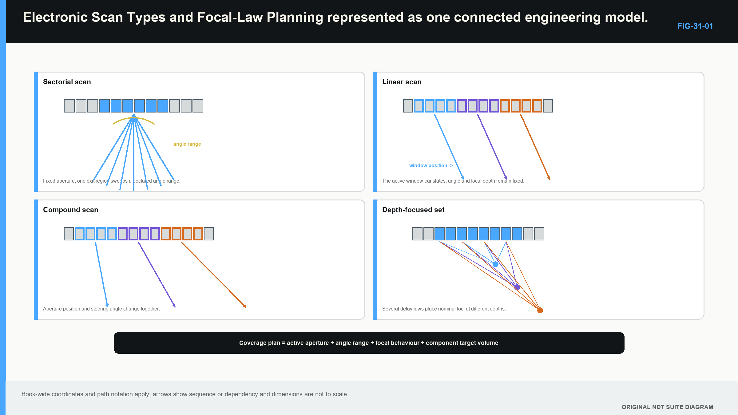
The following figure compares the sequences using the same physical array. Notice that the probe can remain fixed while aperture position, angle or focus changes. [R014] [R016]
31.2 Electronic linear sequence: move the aperture
In a basic electronic linear sequence, the active aperture moves along the array while its selected count, nominal angle, wave mode and focus are kept similar. If the first law uses elements 1 to 10 and the aperture step is two elements, the next law uses elements 3 to 12.
The probe has not moved. The instrument has selected a new virtual probe position within the physical array. This can cover a width without firing every beam from one central aperture. It is useful for straight-beam mapping and for repeating a fixed-angle condition from neighbouring aperture positions.
The electronic step is not the acoustic coverage width. Adjacent apertures can produce fields that overlap strongly, and the first and last positions may be less useful because the physical row ends. Wedge exit position can also change as the active aperture moves. Corrected coordinates need the appropriate reference for each law rather than the centre of the complete probe.
Multiplexing may be needed when the instrument has fewer simultaneous channels than the probe has elements. Multiplexing selects which physical addresses are connected. It does not create the beam by itself; the law delays then coordinate those selected elements.
31.3 Count the complete linear-aperture positions
Before counting, write the first aperture and its element addresses. Then write the proposed step. A law is valid only when the complete selected aperture fits within the available address range.
For a uniform row and fixed number of adjacent active elements:
| (31.1) Law count for a stepped linear aperture · EQ-31-01 Where: N_law = number of complete aperture positions; N_total = available addressable elements; N_active = adjacent elements in each aperture; s = positive step in element positions Model limits: uniform one-dimensional address row; fixed contiguous aperture; first aperture begins at the first available element; incomplete final aperture is not used |
|---|
The subtraction finds how far the aperture start can travel. Division by the step finds the number of complete moves. The floor operation drops any remainder that cannot support another full step. Adding one includes the first aperture before any movement.
For a 48-element row using 10 active elements and a three-element step, the available start travel is 48 - 10 = 38 element positions. Twelve complete three-element moves fit, with a remainder of two. Including the first aperture gives 13 laws. The last starts at element 37 and uses elements 37 through 46. Elements 47 and 48 cannot begin another complete 10-element aperture.
This count assumes every element is available. If damaged elements are excluded or the sequence begins later, count the usable address range and write the actual aperture list. A software preview should be checked against exported first, middle and last element selections.
31.4 Sectorial sequence: change the angle
In a basic sectorial sequence, the aperture position and size remain fixed while the delay pattern changes through an angular range. Each law is intended to interrogate a different direction from a similar probe region.
Define the angle convention before writing the list. In weld PAUT, a refracted angle is often stated from the surface normal inside the component, but instrument conventions vary. Also state wave mode, first and last angle, increment, aperture, focus and wedge/material model.
Smaller angular steps produce more laws and more closely spaced nominal directions. They do not narrow the physical beams. A wide beam can still cause the same reflector to appear over many laws. Conversely, a target with unfavourable orientation may remain weak even when many central rays cross it.
Extreme programmed angles can be limited by element directivity, wedge transmission, critical regions, aperture projection, attenuation and lobe response. A sectorial group is only useful over the range supported by calibration and beam evidence.
31.5 Count a uniformly stepped sector
Write the lower and upper angles with one convention and one unit. A uniformly stepped list includes the first angle. It includes the upper angle only when the selected increment reaches it exactly, unless a separate non-uniform final law is deliberately added.
| (31.2) Law count for a uniformly stepped sector · EQ-31-02 Where: N_law = number of programmed angles; theta_low = first angle (degrees); theta_high = upper angular limit (degrees); Delta_theta = positive uniform angular increment (degrees) Model limits: one declared angle convention; uniform stepping; lower angle included; upper angle included only when an integer number of increments reaches it |
|---|
The floor operation prevents the list from stepping beyond the stated upper limit. If the final endpoint is mandatory and the increment does not reach it, revise the increment or deliberately define a non-uniform last law.
| Worked example · Counting a sector and its multigroup firing demand WE-31-01 Given: A sector includes 40 degrees through 70 degrees in 1-degree increments. Three identical groups are planned at every encoded position. Find: The laws in one group and the total sequential law count. Method: The angular span is 70 - 40 = 30 degrees. At 1-degree steps, there are 30 increments. Include the first angle. N_law = 30/1 + 1 = 31 laws per group N_total = 3 x 31 = 93 laws Answer: Each group contains 31 laws. The three groups contain 93 sequential law firings if each law uses one firing and the implementation adds no repeats. What it means in practice: The count affects complete-set acquisition rate and storage. It says nothing by itself about useful coverage. Common mistake: Counting 30 laws omits one endpoint; assuming 93 simultaneous beams hides the real firing demand. |
|---|
31.6 Focus sweeps and compound sequences
A focus sweep changes focal distance or depth while other main properties are held as planned. Each added transmit focus is normally another focal law. Several focus regions can support a deeper volume, but their sensitivity and resolution can change at the boundaries between them.
A compound sequence changes more than one main property. It may use several angles at several aperture positions. If nine aperture positions, eleven angles and two focal depths are combined at every combination, the result is 9 x 11 x 2 = 198 beam conditions before other groups or repeats are added.
The term compound is used differently by equipment suppliers. Record the active elements, angle, mode, focus and execution order rather than relying on the label. A displayed composite image may also combine data after acquisition without using the same sequence implied by another system's name.
Focus sweeps and compound groups can reduce mechanical passes. They also increase firing count, calibration burden and review complexity. Use them only when the extra beam conditions answer a defined coverage or resolution need.
31.7 Choose the sequence from the examination purpose
Use the same decision path for every proposed sequence:
- Define the target region and likely orientations. State which part of the component and which beam interaction the group supports.
- State what changes. List aperture position, size, angle, mode and focus for the first, middle and last laws.
- Check physical feasibility. Confirm element addresses, channel capacity, wedge paths and usable angle range.
- Map acoustic coverage. Include finite beam regions and target response, not only centrelines.
- Count firing demand. Add every sequential law and group required at one stored position.
- Plan calibration and verification. Make sure every required beam lies inside the demonstrated timing and sensitivity range.
An electronic linear sequence suits a relatively constant angle from several neighbouring virtual positions. A sectorial sequence suits a target population needing angular diversity from one aperture region. A focus sweep suits a depth range that cannot be supported adequately by one focus. A compound group suits a justified combination, not a desire to fill the screen.
For a weld with several fusion-face orientations and a narrow adjacent parent zone, a sectorial group can provide orientation diversity while a fixed-angle electronic linear group covers neighbouring positions. Both groups must be tied to the same component datum. Their combined law count must fit the encoded acquisition plan.
31.8 Plan several groups as one enabled setup
A multigroup setup is verified as a complete enabled configuration. If groups contain 13, 21 and 1 law, the basic total is 35 sequential beam conditions at each complete position. Averaging, pitch-catch arrangements or system scheduling may add more cycles.
Check each group's probe, wedge, mode, range, gates and coordinates. Then check the whole setup for pulse rate, complete-set rate, file demand and display behaviour. A group that works by itself may behave differently when several groups share channel and processing resources.
Name groups by purpose and preserve their identities. A useful record might distinguish “fusion-face angular group,” “fixed-angle root group” and “coupling monitor.” Names such as “Group 1” and “Group 2” are easy to swap during analysis.
The Level 3 chapters extend this planning into resource ledgers, boundary field support, release evidence and immutable law-set traceability. At Level 2, the essential habit is to inspect the actual enabled element and law lists, then connect each group to a practical examination purpose.
Read a small law table before trusting its picture
Consider a 32-element array with an eight-element aperture. A proposed fixed-angle electronic linear group steps the aperture by four elements. The first few rows of a useful law table would state:
| Law | Active elements | Nominal angle | Focus description | What changed |
|---|---|---|---|---|
| 1 | 1-8 | 45 degrees | 25 mm depth | first aperture |
| 2 | 5-12 | 45 degrees | 25 mm depth | aperture moved four elements |
| 3 | 9-16 | 45 degrees | 25 mm depth | aperture moved four elements |
| 4 | 13-20 | 45 degrees | 25 mm depth | aperture moved four elements |
| 5 | 17-24 | 45 degrees | 25 mm depth | aperture moved four elements |
| 6 | 21-28 | 45 degrees | 25 mm depth | aperture moved four elements |
| 7 | 25-32 | 45 degrees | 25 mm depth | final complete aperture |
Table 31.1
The table shows seven complete laws. It also shows that four elements are shared between neighbouring apertures. That shared count does not directly state acoustic overlap, because beam width and focus determine the useful field.
Now compare a sectorial group using elements 13-20 for every law. Its rows might keep active elements and focus description fixed while angle changes from 40 to 70 degrees. The two groups can produce displays of similar width, but their physics differ. The linear group moves the source region. The sectorial group changes direction from one region.
A third group could keep elements 13-20 and 55 degrees while changing focus from 15 to 30 mm. The picture might show several depth regions, but the table reveals the extra sequential firings and the transition between focal conditions.
Read the first, middle and last rows of every group. Confirm that the active element addresses remain valid, that the endpoint angles follow the stated convention and that focus values have one meaning. Then count all enabled rows at one encoded position.
This small table catches errors that a graphical fan can hide. It can expose a missing endpoint, an aperture that overruns the array, an unexpected change in active count, a reversed element sequence or a focus setting that changed with angle. It also gives calibration and analysis a precise law identity.
Plan the law order around the physical purpose
Law execution order can matter even when the same rows are present. An instrument may fire one complete group and then another, or interleave conditions in a supplier-specific way. The displayed sector may not show that timing.
At Level 2, preserve the configured order and use the measured complete-set rate. Do not infer it from view refresh. When one group monitors coupling and another examines the weld, both must still be present at the required stored positions if the technique relies on them.
If a proposed law is excluded because it is weak or physically unsuitable, mark the corresponding coverage consequence. Removing an edge law can improve data quality and rate while narrowing the supported volume. That can be a sound design decision when it is visible, demonstrated and reflected in the scan plan.
Preserve a human-readable group summary beside the exported law list. State the group's purpose, probe side, wave mode, aperture range, angle or focus range, law count and mechanical path. During analysis, this summary helps the reviewer understand why a response appears in one group but not another.
Do not force every group into one display scale. A straight-beam coupling monitor, shear-wave sector and fixed-angle root group can have different useful ranges and response behaviour. Linked review can compare them while retaining their separate identities. Combining their colours without their purposes turns complementary evidence into visual soup.
Practise stating each group in one sentence. For example: “This group keeps a 16-element aperture near the probe centre and steps refracted shear angle from 40 to 70 degrees to examine two fusion-face orientations.” If the sentence cannot state what changes and why, the group is not yet clear enough to defend.
Then state what the group does not cover. The same sector may not provide adequate near-surface separation, passive-plane coverage or sensitivity to an unfavourably oriented target. A fixed-angle stepped aperture may improve lateral placement without adding much angular diversity. These limitations help determine whether another group or mechanical pass has a real purpose.
Finally, compare the group count with the time available at one encoded position. If three groups repeat almost the same physical sensitivity, removing duplication can create acquisition margin. If their directions are genuinely complementary, their added firing demand may be justified. The decision belongs to coverage evidence, not to a preference for either minimal or maximal law count.
In plain words
- Mechanical movement and electronic sequencing are different kinds of scan.
- A linear electronic sequence moves the selected aperture along the array.
- A sectorial sequence changes beam angle through a declared list.
- A focus sweep changes the intended focus region.
- A compound sequence changes more than one main law property.
- Incomplete final apertures are not valid laws.
- Both endpoints count when a uniform angle increment reaches them exactly.
- Every enabled group contributes to acquisition time and review demand.
Key terms
Electronic linear sequence; sectorial sequence; focus sweep; compound sequence; multiplexing; law count; endpoint convention; multigroup.
Key relationships
- fixed angle + stepped aperture -> electronic linear sequence;
- fixed aperture + stepped angle -> sectorial sequence;
- fixed main geometry + stepped focus -> focus sweep;
- available elements, active count and step -> number of complete aperture laws;
- angular span, increment and endpoint rule -> sector law count;
- sum of enabled sequential laws -> basic complete-set firing demand.
Common mix-ups
- An electronic linear sequence is not physical travel along a straight line.
- An S-scan presentation does not prove a sectorial firing sequence.
- Angular increment is not beam width.
- A fractional final aperture is not rounded into a law.
- More laws do not automatically mean better coverage.
Bridge to Chapter 32
Chapter 32 attaches complete law groups to component position. It introduces scan, index and depth coordinates, treats the encoder as a position counter, and connects travel speed with the rate needed to collect every law at every stored position.
Sources and further study
- [R014]
- [R016]
- [R042]
Study and revision only. This is not an approved inspection procedure, acceptance criterion or qualification.