
CHAPTER 54 · FMC / TFM / PCI Level 2
From Valid Data to a Reproducible Conclusion
In this chapter · 23 sections
Why this matters
Several matrix views can support one planar indication while giving different apparent shapes and sizes; a defensible conclusion does not begin with the favourite image. It begins with valid source data, a plausible path and a controlled reconstruction. Detection, location, characterisation, sizing and evaluation are then kept separate. The record must preserve enough acquisition, waveform, view and measurement evidence for another authorised reviewer to reproduce the reported result. Provenance is therefore part of the measurement, not filing performed after the technical work.
What you already need
- The Chapter 53 proof gates and artefact diagnostic sequence.
- Path, pixel, grid, aperture and coherence limits from Chapters 49 to 52.
- PAUT indication review, sizing and reporting foundations.
- The difference between an observed indication, a discontinuity interpretation and an acceptance decision.
- Confidence using subtraction and a supplied uncertainty relationship.
What you will learn
- Keep detection, localisation, characterisation, sizing and evaluation distinct.
- Review a feature through path, raw waveform and complementary-view evidence.
- Apply supported tip, length, amplitude or geometry sizing boundaries.
- Combine two boundary-position uncertainties using a supplied relationship.
- Preserve source files and a reproducible reconstruction recipe.
- Build a restrained report and identify decisions outside Level 2 authority.
Words you will meet
- Detection: supported statement that a response meeting a defined review condition is present.
- Localisation: assignment of a coordinate or bounded region under a declared path model.
- Characterisation: supported description of what a response is most consistent with.
- Sizing: estimate of a physical dimension using an authorised method.
- Evaluation: comparison of a reportable result with the governing acceptance source.
- Provenance: retained identity and history connecting source data, processing and conclusion.
- Correlation: tendency of two errors to change together rather than independently.
54.1 Begin by proving that the data are fit to interpret
Open the locked source dataset and its controlled setup. Confirm component, weld or area, datum, scan side, physical extent, probe and wedge, acquisition scheme, encoder direction, software version and pre-use and post-use results. Review coupling, matrix health, clipping, time support and stored-position continuity before examining an indication in detail. This order matters. An invalid acquisition cannot be rescued by agreement between several images made from it. A physically impossible path cannot become plausible because PCI and amplitude TFM both display a feature from the same mis-modelled data.
The matrix-imaging literature and technical sources emphasise the link among explicit path, retained data, reconstruction settings, multi-view evidence, sizing method and reproducible reporting. [R018] [R019] [R047] [R048] [R050] [R061] The following figure shows that chain. Notice that the report remains connected all the way back to the matrix and its component coordinates.
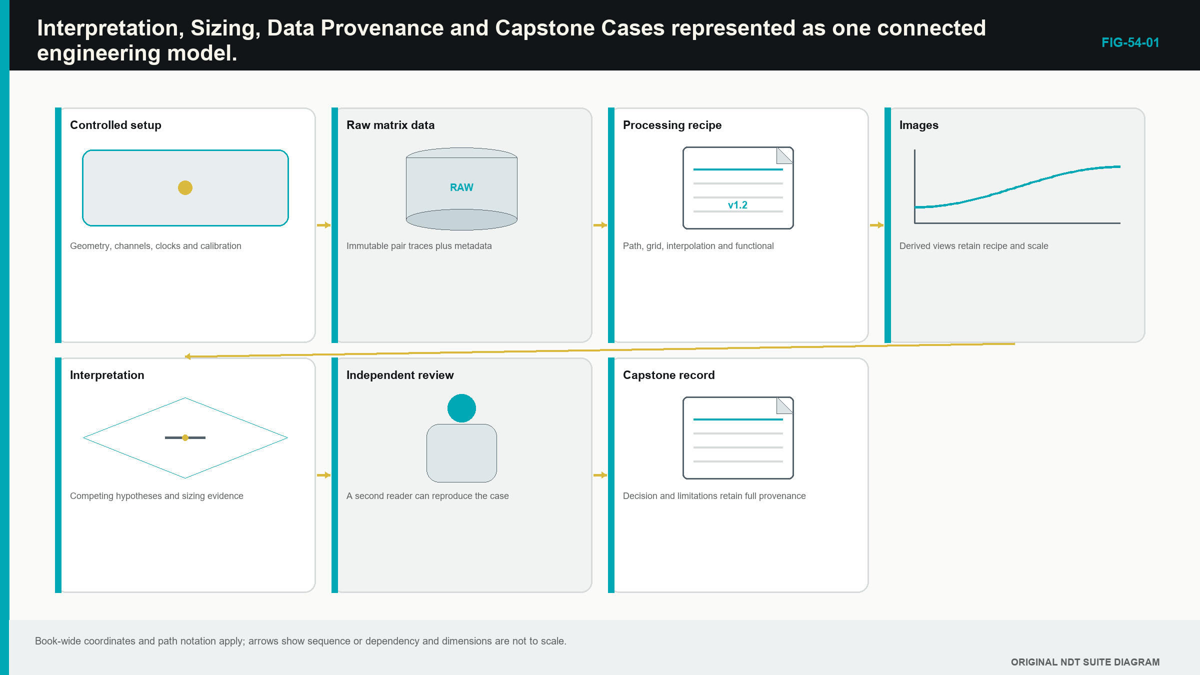
Once the source record passes its defined checks, the learner can review features; the check does not prove that each feature is relevant. It establishes that later reasoning begins from valid evidence.
54.2 Keep five decisions separate
Detection states that a response meeting the technique's review condition exists; it does not name the cause, physical size or acceptance status. A response can appear in only one valid view because target orientation and path sensitivity differ.
Localisation places the response in the component coordinate system. Timing, velocity, wedge and surface model, element location, encoder registration, grid and point-spread behaviour affect the result. Cursor decimals do not create demonstrated coordinate accuracy.
Characterisation states what the response is most consistent with. Categories can include known geometry, volumetric scattering, planar or tip-like behaviour and relevant discontinuity; when alternatives remain, restrained wording preserves them. A phrase such as response consistent with upper and lower diffracting features is more defensible than crack tips when reflector identity has not been demonstrated.
Sizing estimates a physical dimension using an authorised method. Tip positions, geometric endpoints, amplitude thresholds and encoded limits are different methods with different assumptions. Image width alone combines target scattering, point-spread response and processing, so it is not automatically flaw width.
Evaluation compares the reportable result with a controlled acceptance source. TFM, PCI and a red colour do not create acceptance criteria; the report identifies the governing rule and the person assigned to make the decision.
54.3 Review one indication in a repeatable sequence
Assign an indication identifier (ID) and read its component coordinates. Record the view, path family, image domain, scale and encoded range. Draw the transmit and receive legs, including modes, reflections and conversions. Open representative supporting pair A-scans; their amplitudes need not match because pair angle, directivity, path transmission and reflector orientation vary. Their timing should support the declared path across a useful aperture. Clipping, cross-talk, ring-down and one dominant channel are challenged directly.
Compare the amplitude and phase-coherence products using their separate fixed scales. Add a complementary path only when it changes the physical interaction. Test known geometry, alternative mode, multiple, lobe, model error and data-quality explanations. Observe movement as the probe advances and repeatability after lift-and-replace where the technique uses it. Characterise only to the level supported by this combined evidence. Apply a sizing method only when its prerequisites are met. Record ambiguity and unexamined areas. Evaluation occurs last and within assigned authority.
The sequence keeps an image from becoming its own proof; it also provides an efficient review record because every captured screen and waveform has a stated purpose.
54.4 Use convergence and contradiction correctly
Two reconstructions from the same source data can be strongly correlated; if their path, aperture and processing are similar, agreement is useful but not independent confirmation. Stronger corroboration can come from a materially different path, another scan surface, conventional phased array or ultrasonic testing (UT), a known component boundary or a repeat acquisition. Create a comparison record rather than scrolling between screenshots from memory. For each view, record coordinate, path, output domain, fixed scale, expected scattering behaviour, source support and credible alternative cause.
Convergence means valid views place compatible evidence at the same physical feature under their expected response mechanisms; it does not require identical brightness or shape. A face-dominant amplitude view and tip-dominant PCI view can converge in coordinate and physical interpretation. Contradiction is evidence. Direct and reflected views that place a claimed feature at incompatible depths may reveal wrong velocity, thickness, surface or path. A PCI tip pair coincident with known root geometry needs both explanations retained. A silent view expected to detect the target weakens the case only when that view has demonstrated sensitivity for the location and orientation.
Material contradiction that could change a reportable conclusion is a hold point for authorised review. Selecting the display that supports a preferred answer is not multi-view interpretation.
54.5 Size only the dimension the method supports
Tip-to-tip sizing uses two demonstrated boundary responses. When the upper and lower tip coordinates share one depth convention, through-wall height is their absolute difference.
| (54.1) Tip-to-tip through-wall height · EQ-54-01 Where: h = indicated through-wall height (mm or m); z_lower = qualified lower-tip depth coordinate in the same unit; z_upper = qualified upper-tip depth coordinate in the same unit Model limits: both responses are demonstrated physical tips of the same feature, use one component frame and lie within the authorised sizing method |
|---|
The subtraction is simple; the interpretation is not. A lower corner response is not automatically the lower crack tip. Two coherence hot spots are not automatically connected. The evidence package identifies the points, paths, domains and reason they represent the intended boundaries. Encoded length uses positions where a qualified response condition is met. Scan increment, point-spread extent, skew, curvature, endpoint rule and repeatability affect the value. A smoothed colour region can extend beyond the reflector.
Amplitude-drop and threshold methods apply only to controlled amplitude-domain data. They require linear source acquisition, defined sensitivity or reference behaviour and a demonstrated relationship to the target. A phase-only scale or independently normalised image cannot supply a conventional decibel drop. Geometric methods use known surfaces, path intersections or paired features. They depend on accurate component geometry, thickness, velocity and probe registration. Precise cursors can remain systematically wrong when the surface model is wrong.
54.6 Treat uncertainty as more than pixel spacing
Position uncertainty can include time origin, sampling and interpolation, material speed, temperature, wedge and surface geometry, element coordinates, encoder scale and zero, point-response width, target orientation, path identity, endpoint rule and analyst repeatability.
Some errors affect upper and lower boundary positions together. A shared time-zero or geometry bias can move both in the same direction. This shared behaviour is correlation. It can partly cancel in the height difference, while independent cursor spread contributes separately.
For two boundary estimates in a common frame, a supplied relationship can combine their standard uncertainties and correlation:
| (54.2) Two-boundary height uncertainty · EQ-54-02 Where: u_h = standard uncertainty of indicated height (mm or m); u_top = upper-boundary position standard uncertainty in the same unit; u_bottom = lower-boundary position standard uncertainty; corr_tb = correlation coefficient between the boundary-position errors (dimensionless, from -1 to +1) Model limits: height is the difference between two boundary locations, the uncertainty values use a compatible standard basis and the stated correlation represents shared behaviour |
|---|
| Worked example · Height from two reconstructed tips WE-54-01 Given: Demonstrated upper and lower tip responses are at 12.3 mm and 18.1 mm depth. Each coordinate has 0.5 mm standard uncertainty, and correlation is neglected for this calculation. Find: The indicated height and its standard uncertainty. Steps: Height is 18.1 mm - 12.3 mm = 5.8 mm. With corr_tb = 0, calculate u_h = sqrt((0.5 mm)^2 + (0.5 mm)^2) = sqrt(0.50 mm^2) = 0.71 mm. Answer: The indicated height is 5.8 mm with about 0.7 mm standard uncertainty under the stated model. What it means in practice: The numeric result does not resolve whether the responses are true tips, whether grid bias is shared or whether the method is authorised for this target. Common mistake: Reporting 5.80 mm with implied hundredth-millimetre confidence ignores the demonstrated coordinate uncertainty. |
|---|
The organisation's approved uncertainty and reporting method remains the authority. At minimum, the Level 2 result avoids false precision and states known limitations. Formal correlated uncertainty belongs in Chapter 63 and Chapter 78.
54.7 Control the field record from the start
Before scanning, confirm the released instruction, component identity, material and thickness range, surfaces, extent, datum, acceptance source and approval status. Inspect temperature, coating, access and obstructions. Mark origin and positive direction so they can be checked independently of the display.
Match instrument, probe, wedge, scanner, cables and software to the controlled setup. Confirm power, storage, file location and unique naming. Complete required equipment, setup and application checks. A familiar file name is not evidence that the current revision is approved.
During scanning, monitor coupling or a suitable interface channel, element condition, clipping, useful source level, encoder position, direction and continuity, scan speed, physical contact, overlap, file growth and environment. PCI background is not used as coupling proof when that processing suppresses broad interface energy.
If coupling is lost, pause at a traceable point, correct it and repeat the affected segment with the required overlap. At each line end, compare stored and physical positions. Review required paths promptly while access remains available.
Complete post-use checks before releasing the setup. A failed check quarantines data back to the last valid state under the controlled disposition. The aim is to discover acquisition loss while the component can still be rescanned.
54.8 Preserve source identity and a reconstruction recipe
A file name must remain unique after leaving its original folder. Link job and component, weld or area, scan side, pass, datum, direction, sequence, setup revision and operator or instrument record. A raw file called Scan1 becomes ambiguous as soon as somebody copies it into another project.
Transfer the source dataset without alteration. Copy the acquisition setup, reference records, encoder and auxiliary channels. Verify file count, size and integrity by the organisation's method. Record source and destination. Restrict write access to the preserved original and work on a controlled copy.
The reconstruction recipe links source dataset and encoded range; software, firmware and algorithm version; probe, wedge and element map; matrix, sampling, range, gain and filters; material speed, thickness and surface model; path and pair aperture; ROI and grid; interpolation, envelope, weights and normalisation; PCI implementation and controls; display range; author, reviewer and revision.
This retained identity and history is provenance. It allows another authorised person to recreate the reported image and understand every material change. A screenshot and setup title alone do not provide it.
If conversion discarded amplitude or pair detail, state that loss. A single-bit phase record cannot later produce ordinary amplitude TFM unless separate full-waveform data were retained.
54.9 Report observation before conclusion
The examination identity and scope section states component, area, datum, surface, scan extent, technique revision, equipment and personnel status. It states limited or unexamined areas plainly.
The observation section gives indication ID, component coordinates, encoded extent, path and output domain. It describes the displayed evidence without inserting unsupported flaw type or acceptance language.
The interpretation section explains geometry exclusion, source support, complementary views and any characterisation. It links fixed-scale images and representative A-scans. Credible unresolved alternatives remain visible.
The sizing section names the authorised method, measured dimension, coordinate convention, repeated result and uncertainty or limitation. It separates image endpoints from physical flaw endpoints unless evidence validates the relationship.
The evaluation section cites the controlled acceptance source and assigned decision-maker. When the Level 2 examiner lacks authority, the technical result is routed without an invented accept or reject label.
The traceability section lists source, setup, recipe, checks and software version. It records coverage gaps, material difficulty, ambiguous evidence and approved departures. The report is strongest when a reviewer can reproduce a selected image and trace its conclusion back to valid source waveforms.
54.10 Reprocess, rescan, amend and retain
Reprocessing can be appropriate when complete valid source data support an authorised recipe change. The old and new recipes, reason, authority, affected indications and review outcome are recorded. Earlier derived images are not deleted.
Rescanning is required when acquisition evidence is invalid or absent, including lost coupling, clipping, insufficient time range, encoder gaps, wrong physical scan location, excessive unavailable channels or an unresolved failed post-use check.
An amended report identifies the superseded issue, reason, changed fields, supporting evidence, reviewer, approver and distribution. Quietly replacing an issued report file or database value destroys the review chain. Correcting a typographical identifier and changing an indication height can follow different approval routes because their technical consequences differ.
Retention follows the project and organisation schedule. Keep source or losslessly recoverable data, metadata, checks, setup revisions, recipes, images, worksheets, report and amendment history as required. Record format migrations and preserve an approved reader or export when a proprietary file depends on specific software.
Archived records are periodically checked for readability. An immaculately controlled file that no authorised system can open has achieved the rare state of certified archaeology.
54.11 Integrated Level 2 case
A learner receives a released training instruction for an encoded weld specimen. The objective is to detect and locate defined planar and volumetric targets, use a demonstrated tip method where prerequisites are met, and prepare evidence for authorised evaluation. Component drawing, datum, material range, probe, wedge and acceptance-source extract are controlled.
The setup uses a declared FMC matrix, complete time support and one direct plus one reflected view. Amplitude TFM and PCI recipes share source data, path geometry, ROI and grid. Channel, timing, encoder and known-target checks pass. A performance specimen confirms central, near-surface and backwall-adjacent behaviour, including the different appearance of a planar face and tips.
During acquisition, one coupling interruption occurs. The learner stops at a known coordinate, restores contact and repeats the segment with overlap. The interrupted section remains marked non-reportable. Post-use checks pass, and raw data, setup and auxiliary records are transferred with integrity evidence.
Interpretation on a controlled copy identifies one compact volumetric response, one planar indication with two supported tips and one coherent root response. The root response is rejected as non-relevant after component-coordinate movement, geometry prediction and a complementary path agree. The planar face is stronger in amplitude TFM; its ends are clearer in PCI. Source traces confirm usable unclipped signal.
Tip height is calculated, repeated and reported with the demonstrated uncertainty. The learner does not apply a decibel-drop rule to PCI and does not decide acceptance. The final package links source matrices, paths, recipes, fixed-scale images, A-scans, sizing worksheet, limitations and approval status.
A peer reviewer reproduces one reported image from the protected source and recipe. One missing display-range field is found, corrected through revision and retained in the audit history. The case demonstrates the complete crossover while keeping the teaching flow focused on evidence, reproducibility and traceable review.
54.12 Level 2 completion and authority boundary
The completed Level 2 learner can follow a defined acquisition, audit source data, explain one-pixel reconstruction, compare justified paths, use amplitude and coherence domains correctly, recognise common artefacts, apply an authorised sizing method and assemble reproducible evidence.
The learner does not approve new acquisition architectures, algorithms, paths, essential-variable ranges, sizing methods or acceptance criteria. Those tasks require the designated Level 3 or other authorised technical authority. A change outside the demonstrated range is recorded and escalated before production use.
Part VII begins by revisiting the same source data at Level 3. It asks how acquisition architecture changes retained information, how reconstruction algorithms are compared, how paths are validated and how reliability and software change are defended. The practical picture developed in Part VI remains the foundation.
Step up
Chapters 55 to 63 cover acquisition design, reconstruction functionals, path solvers, computation, advanced coherence, optimisation, reliability, forensics and governance. Chapters 72, 78 and 80 provide engineering depth for image comparison, uncertainty and controlled data systems.
In plain words
- Valid source data and plausible paths come before interpretation.
- Detection, localisation, characterisation, sizing and evaluation are separate decisions.
- Agreement among correlated views is not the same as independent evidence.
- A sizing number is valid only for the dimension and method demonstrated.
- Uncertainty includes timing, geometry, path, target response, encoder and analyst effects.
- Provenance links source data, reconstruction settings, evidence and report.
- Reprocessing needs valid retained data; acquisition loss normally requires rescanning.
- Acceptance remains with the governing source and assigned authority.
Key terms
- Detection: defined response present.
- Localisation: response assigned to a bounded component coordinate.
- Characterisation: supported description of likely response type or source.
- Sizing: authorised estimate of a physical dimension.
- Evaluation: comparison with a governing acceptance rule.
- Provenance: retained identity and history of data and processing.
- Correlation: shared movement of two error contributions.
Key relationships
- h = |z_lower - z_upper|: tip height is the difference between demonstrated boundary coordinates.
- u_h = sqrt(u_top^2 + u_bottom^2 - 2 corr_tb u_top u_bottom): shared error changes the uncertainty of a boundary difference.
- source data + recipe + version -> reproducible image: all three are needed to recreate reported evidence.
- observation -> interpretation -> sizing -> evaluation: each step adds a distinct claim and authority boundary.
Common mix-ups
- A detected response is not automatically a characterised defect.
- Image width is not automatically physical flaw width.
- Pixel spacing is not the whole measurement uncertainty.
- Several displays from one dataset are not automatically independent evidence.
- A method output does not create acceptance criteria or technical authority.
Bridge to Part VII
Part VI has built the matrix-imaging crossover from one stored A-scan to one pixel, a complete image, complementary coherence and a reproducible conclusion. Part VII begins Level 3 by comparing what different acquisition architectures retain and lose. The familiar Level 2 evidence chain becomes the basis for technical design and validation.
Sources and further study
- [R018]
- [R019]
- [R047]
- [R048]
- [R050]
- [R061]
Study and revision only. This is not an approved inspection procedure, acceptance criterion or qualification.