
CHAPTER 1 · Materials All levels
Materials Knowledge in the NDT Decision Chain
In this chapter · 7 sections
Learning outcomes
After completing this chapter, the learner should be able to explain why product technology changes the probability and orientation of discontinuities; distinguish material, process, service and inspection information; separate an indication, discontinuity and defect; choose preliminary NDT methods from material, location and access constraints; and identify decisions that require engineering or Level 3 authority.
1.1 From component history to inspection hypothesis
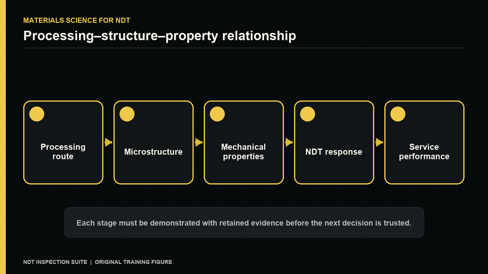
An NDT examination begins before the equipment is switched on. The component has a history: raw material was melted or consolidated, shaped, joined, finished, loaded and exposed to an environment. Each stage creates a different population of possible conditions. A casting can contain shrinkage or gas porosity. Rolled plate can contain elongated inclusions or laminations. A weld can contain incomplete fusion, solidification cracking or hydrogen-assisted cracking. Service can add fatigue, corrosion, creep damage, erosion or wear.
Product knowledge converts that history into an inspection hypothesis. The technician asks what could exist, where it would form, how it would be oriented, which surface can be accessed and which method can produce useful evidence. This is more defensible than applying a familiar technique and hoping that all important conditions politely face the probe.
Four information groups should be kept separate:
- Material information: grade, product form, composition range, heat treatment, mechanical properties and magnetic or electrical behaviour.
- Process information: casting route, reduction direction, forging flow, weld process, joint preparation, machining and surface treatment.
- Service information: load type, cycles, temperature, pressure, environment, contact, previous repairs and time in operation.
- Inspection information: required volume, expected discontinuities, access, surface condition, sensitivity, coverage, acceptance source and reporting rules.
Missing information is itself a finding. If grade, geometry or heat treatment is uncertain, the technician should record the limitation and obtain direction instead of silently selecting the most convenient assumption.
1.2 Indication, discontinuity and defect
An indication is evidence produced during an examination. It may come from geometry, a material boundary, a test artefact or a discontinuity. Interpretation assigns a likely cause. A discontinuity is an interruption in the normal physical structure or configuration. It can be intentional, harmless or significant. A defect is a condition judged unacceptable by the applicable criteria.
The sequence is therefore:
observed response -> interpretation -> relevant discontinuity -> evaluation -> acceptance or rejection
Calling every response a defect skips the technical work and the authority boundary. Conversely, calling a clear relevant response "just an indication" after evaluation criteria have been exceeded is equally poor practice.
1.3 Method selection as a materials problem
Visual and penetrant testing address accessible surfaces; penetrant requires a clean, non-porous surface and an opening connected to it. Magnetic particle testing requires a ferromagnetic material and a suitable magnetising direction. Eddy current testing requires electrical conductivity and is strongly affected by conductivity, permeability, geometry and lift-off. Ultrasonic testing depends on sound transmission, grain structure, geometry and reflector orientation. Radiography responds to changes in transmitted radiation and is often effective for volumetric conditions, while fine planar conditions can be difficult when unfavourably aligned.
Method selection must consider the condition's likely location and orientation. Surface fatigue cracking in a non-ferromagnetic alloy may favour PT or ET. Deep lamination in plate may favour straight-beam UT. Distributed casting porosity may be evident radiographically, while coarse grains may make UT noisy. Combining methods is often the best answer because different physical principles fail in different ways.
1.4 Level 2 field checkpoint
Before planning a test, prepare a one-page component history:
- Identify the product form and manufacturing route.
- Mark changes in section, joints, heat-affected regions and worked directions.
- List credible manufacturing and service discontinuities.
- Predict their location, orientation and surface connection.
- Compare at least two NDT methods and state their limitations.
- Identify the governing acceptance source and any missing information.
Escalate when the material is outside demonstrated capability, access prevents required coverage, geometry creates an unresolved blind zone, acceptance criteria are absent, or the requested conclusion exceeds NDT evidence.
Common errors and misconceptions
Several common errors recur in this topic: selecting a method because the equipment is available rather than because the physics fits; assuming a certificate proves the identity of the item in front of you without traceability; treating a discontinuity name as an acceptance decision; ignoring manufacturing direction when predicting reflector orientation; and reporting complete coverage when part of the required volume was inaccessible.
Chapter summary
Materials knowledge turns component history into credible inspection targets. Method choice depends on material, geometry, access, location and orientation. NDT produces evidence; interpretation identifies likely causes; the governing criteria determine acceptability. Honest limits are part of a valid examination.
Study and revision only. This is not an approved inspection procedure, acceptance criterion or qualification.