
CHAPTER 16 · Materials All levels
In-Service Degradation, Corrosion and Integrity Decisions
In this chapter · 11 sections
Learning outcomes
The learner should be able to explain major corrosion cells and morphologies, compare fatigue, creep, wear and environmentally assisted cracking, predict vulnerable locations, choose monitoring methods and separate NDT findings from engineering fitness decisions.
16.1 Electrochemical corrosion
An electrochemical corrosion cell requires an anodic reaction, a cathodic reaction, an ionic path through an electrolyte and an electronic path through the metal or connection. Metal loss occurs at anodic sites. Remove or control one essential element and the cell is interrupted or reduced.
Uniform corrosion spreads broadly. Galvanic corrosion occurs when dissimilar electrochemical behaviour is coupled in an electrolyte; area ratio matters because a small anode feeding a large cathode can attack rapidly. Pitting produces local penetration after passive-film breakdown. Crevice corrosion develops where restricted mass transfer creates a different local chemistry. Intergranular attack follows susceptible grain-boundary regions. Selective leaching removes one alloy constituent. Microbiologically influenced corrosion changes local electrochemistry through biological activity. Erosion-corrosion combines fluid mechanics with chemical attack.
Corrosion rate may be estimated from mass loss using a controlled form such as:
rate = K W / (rho A t)
where W is mass loss, rho density, A exposed area, t time and K a unit constant. The formula depends on valid cleaning and exposure data and does not describe the deepest local pit.
16.2 Protection and monitoring
Protection includes material selection, design to avoid traps and galvanic couples, coatings or linings, inhibitors, environmental control, cathodic protection and corrosion allowance. Coatings can conceal under-film damage. Cathodic protection requires potential and current control; excessive or inadequate protection introduces different risks.
Monitoring may use VT, thickness UT, encoded corrosion mapping, profile radiography, guided waves, ET, MFL, coupons, probes and process data. Repeat measurements require stable datums, comparable technique and uncertainty. Apparent wall growth is usually a measurement warning, not a miracle of pipe nutrition.
16.3 Fatigue and fracture
Fatigue begins with cyclic damage, usually at a surface, notch, weld toe, inclusion or other stress concentration. A small crack initiates, propagates over many cycles and leaves a final overload region. Mean stress, stress range, surface, environment, residual stress and geometry affect life. Corrosion fatigue combines cyclic loading with environment and can remove a clear endurance limit.
Brittle fracture can propagate rapidly with little gross deformation when stress, crack-like condition, low toughness and temperature align. Ductile tearing absorbs more energy and often shows plastic deformation. NDT detects and sizes conditions within capability; engineering assessment determines remaining strength and allowable service.
16.4 Creep, stress-corrosion and high-temperature damage
Creep is time-dependent deformation under sustained stress, significant at elevated homologous temperature. Primary creep rate decreases, secondary creep is approximately steady, and tertiary creep accelerates toward rupture. Cavities can form at grain boundaries and link into cracks. Weld heat-affected zones may have different creep strength from base and weld metal.
Stress-corrosion cracking requires a susceptible material, specific environment and tensile stress. Cracks may be branched and can develop with little general metal loss. Hydrogen damage includes blistering, hydrogen-induced cracking and embrittlement mechanisms depending on material and environment. The exact mechanism requires materials and service evidence, not crack shape alone.
16.5 Wear and contact damage
Adhesive wear transfers material between contacting surfaces. Abrasive wear cuts or ploughs material with hard asperities or particles. Fretting occurs under small oscillatory movement and can combine wear, oxidation and fatigue. Cavitation damage comes from repeated bubble collapse in a liquid. Erosion results from particles or droplets striking a surface. Lubrication, alignment, hardness, particle control and geometry influence these mechanisms.
16.6 Level 2 integrity workflow
- Confirm service history and damage mechanism assumptions.
- Identify high-stress, high-temperature, wet, shielded and contact locations.
- Select detection and sizing methods demonstrated for the morphology.
- Establish repeatable coordinates and baseline data.
- Record coverage, uncertainty and change over time.
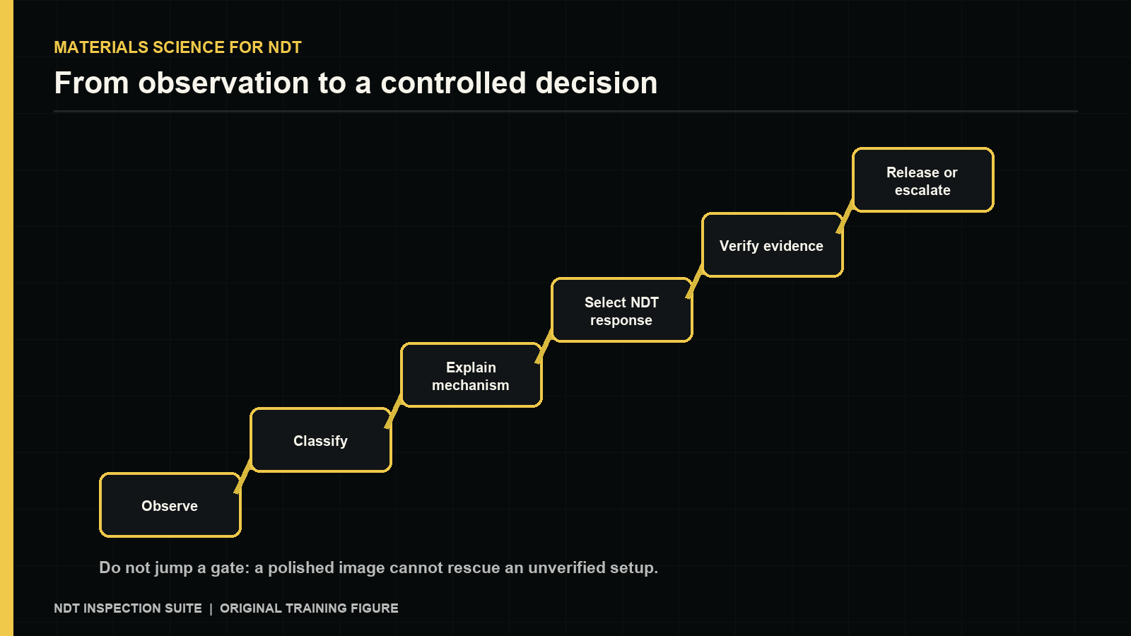
- Escalate findings for engineering evaluation using the governing integrity process.
NDT personnel should not convert a remaining-wall reading into a run/repair decision unless specifically authorised under an approved assessment process.
Common errors and misconceptions
Several common errors recur in this topic: reporting minimum average wall when the concern is a deep local pit; calling every branched crack stress-corrosion cracking; comparing monitoring surveys with different datums or calibration; ignoring a coating because the exposed surface looks sound; and making a fitness-for-service decision from NDT data alone.
Chapter summary
Service degradation couples material, stress, time and environment. Corrosion takes many morphologies; fatigue, creep, SCC and wear require different inspection strategies. Repeatable monitoring is as important as one-off detection. Engineering authority evaluates fitness, while Level 2 NDT supplies traceable evidence and limitations.
Closing field checklist
Before completing a materials-informed examination, confirm that the component identity, product form, process history, heat treatment, service exposure, expected discontinuities, access, calibration basis, acceptance source and reporting datum are controlled. Record uncertainty where evidence ends. A technically modest report with traceable facts is more useful than a confident metallurgical fairy tale.
Controlled references to verify before approval
The approving organisation should establish a current controlled reference register covering certification requirements; material and product specifications; welding and heat-treatment documents; mechanical-test methods; terminology; penetrant, magnetic, ultrasonic, radiographic and electromagnetic method standards; corrosion and fitness-for-service processes; and manufacturer instructions. Edition numbers are intentionally omitted until verified through document control.
Study and revision only. This is not an approved inspection procedure, acceptance criterion or qualification.