
CHAPTER 1 · Phased Array Ultrasonics Level 2
The PAUT Level 2 Practitioner
In this chapter · 10 sections
Learning outcomes
After completing this chapter, the learner should be able to:
- explain how NDT contributes to quality, reliability and safety;
- compare the basic capabilities and limitations of common NDT methods;
- explain why method selection must be based on material, geometry, discontinuity and access;
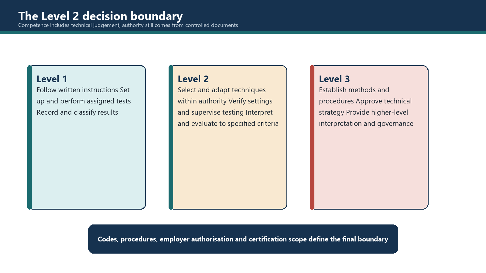
- distinguish the typical responsibilities of Level 1, Level 2 and Level 3 personnel;
- describe the technical and documentary responsibilities expected at Level 2;
- identify decisions that must remain within employer authorisation and approved documents.
Key terms
Non-destructive testing (NDT): Examination of a component or material without making it unusable for its intended purpose.
Method: A discipline based on a physical principle, such as ultrasonic, radiographic or magnetic particle testing.
Technique: The specific way a method is applied to a component and inspection objective.
Indication: A response or piece of evidence produced by an NDT examination.
Interpretation: Deciding what is likely to have caused an indication.
Evaluation: Comparing a relevant indication with the applicable reporting or acceptance rules.
Procedure: An approved document that defines the controlled requirements for applying a method or range of techniques.
Work instruction: A job-specific set of directions derived from the applicable procedure and governing documents.
1.1 NDT as a quality and safety tool
Manufacturing and service both introduce uncertainty. A weld may contain incomplete fusion, a rolled plate may contain laminations, a casting may contain shrinkage, and a component in service may develop corrosion or fatigue cracking. Destructive testing can provide valuable information, but the tested item is cut, loaded, broken or otherwise made unsuitable for service. NDT is used when information is needed from the actual component without deliberately destroying it.
That difference allows an organisation to examine production items, inspect internal or surface conditions, retain evidence, and repeat an examination during service. The practical value is not simply that NDT finds flaws. Properly planned NDT supports decisions: whether a component may proceed, whether more examination is required, whether a repair is acceptable, or whether a change over time needs action.
NDT is common in sectors where failure can have serious consequences, including oil and gas, petrochemical processing, power generation, transport, aerospace, pipelines and heavy manufacturing. The method must still be suitable for the task. An impressive display cannot compensate for poor access, unsuitable material, incorrect beam orientation or an inspection volume that was never covered.
1.2 Choosing a method by the inspection problem
No NDT method is universally best. Each method responds to different physical conditions and has different needs for access, surface condition, material properties and operator skill.
| Method | Strong applications | Important constraints |
|---|---|---|
| Visual testing (VT) | Rapid examination of accessible surfaces, alignment, condition, workmanship and visible damage; direct or remote viewing may be used | Requires suitable access, lighting and viewing conditions; cannot directly reveal hidden internal conditions |
| Penetrant testing (PT) | Surface-breaking discontinuities in suitable non-porous materials; portable and comparatively simple | Detects only openings connected to the surface; requires careful cleaning and controlled chemicals; unsuitable for porous surfaces |
| Magnetic particle testing (MT) | Surface and some near-surface discontinuities in ferromagnetic material; rapid visible results | Limited to ferromagnetic material; magnetisation direction matters; demagnetisation or additional surface preparation may be required |
| Eddy current testing (ET) | Surface and near-surface response in electrically conductive materials; can work through some coatings and can be automated | Sensitive to conductivity, permeability, geometry and lift-off; requires interpretation and is not suitable for non-conductors |
| Ultrasonic testing (UT) | Internal examination, depth/location measurement, thickness measurement and detection of favourably oriented planar reflectors; portable and free from ionising radiation | Coupling and surface condition matter; coarse grain and complex geometry can reduce performance; response depends strongly on reflector orientation and operator competence |
| Radiographic testing (RT) | Permanent image and useful response to thickness or density changes, particularly many volumetric conditions | Uses ionising radiation; often requires access arrangements around both sides; fine planar discontinuities may be poorly oriented; inspection and interpretation can be slow and costly |
Advanced or specialised approaches include PAUT, time-of-flight diffraction, infrared thermography, shearography, digital or computed radiography, and acoustic emission. Calling a method advanced does not make it automatically superior. It normally means the equipment, data processing or application is more specialised. Suitability still comes from the inspection objective.
1.3 Where PAUT fits
PAUT belongs to the ultrasonic method. It uses multiple elements and controlled time delays to create, steer, focus or move an ultrasonic beam electronically. That provides options that a fixed-angle single-element probe cannot provide from the same footprint. A PAUT setup may collect many A-scans at different angles or positions, combine them into image presentations, and record encoded positional data for later analysis.
Those capabilities can improve coverage, repeatability and characterisation, but they also increase the number of decisions that must be correct. Probe and wedge data, focal laws, material velocity, scan coordinates, calibration, acquisition rate and display interpretation all interact. PAUT is therefore not a shortcut around conventional UT knowledge. It is conventional ultrasonic physics applied through a more flexible transmitter, receiver and data system.
For a Level 2 practitioner, the important question is not, "Can the unit make a colourful sector scan?" The important questions are:
- Does the sound reach the required inspection volume?
- Are the expected discontinuities favourably insonified?
- Has each required beam been calibrated and verified?
- Is the scanner collecting data at a rate that prevents gaps?
- Can the indication be located and characterised using the available views?
- Which controlled criteria apply to reporting and acceptance?
1.4 Qualification levels and responsibility
Certification demonstrates competence within a stated method, level and sector. It does not by itself authorise every inspection. The employer normally defines what a certified person is authorised to perform, and the work must remain within the scope of that authorisation.
Level 1
A Level 1 person typically works to a written instruction and under appropriate supervision. When authorised, the person may set up specified equipment, carry out the examination, record results, classify them using written criteria, and report the results. Level 1 is an execution role. Selecting the method or technique and independently interpreting results are outside the normal Level 1 boundary.
Level 2
A Level 2 person is expected to apply the method using approved procedures and exercise controlled technical judgement. Depending on certification scope and employer authorisation, Level 2 responsibilities may include:
- choosing an appropriate technique within the nominated method;
- identifying application limits caused by material, geometry, access or equipment;
- converting requirements from procedures, standards, codes and specifications into a usable work instruction;
- setting up the system and confirming that settings and calibrations are valid;
- performing and supervising examinations;
- interpreting indications and evaluating relevant results against the applicable criteria;
- completing or supervising tasks at Level 1 and Level 2;
- guiding personnel working at or below Level 2;
- producing clear, traceable reports.
Level 2 authority is substantial, but it is not unlimited. A Level 2 person should not invent acceptance criteria, waive a mandatory calibration, silently change an approved technique, or claim coverage that the scan plan does not demonstrate.
Level 3
A Level 3 person carries broader responsibility for the method. The role may include directing NDT operations, interpreting codes and standards, selecting methods and procedures, establishing or validating instructions, taking responsibility for a facility, and providing technical guidance at all levels. Level 3 knowledge also extends to materials, fabrication, product technology and the general capabilities of other NDT methods.
The three levels should not be viewed as a ladder where each person simply presses more buttons. The difference is the type and consequence of the decisions each level is competent and authorised to make.
1.5 The Level 2 decision chain
A reliable Level 2 inspection can be thought of as a chain of linked decisions.
Step 1: Define the inspection objective
Identify the component, material, geometry, manufacturing process, inspection area and discontinuities of concern. Determine whether the task is detection, location, characterisation, sizing, acceptance evaluation, monitoring, or a combination.
Step 2: Identify the governing documents
Confirm the approved procedure, work instruction, method standard, product code, client specification and drawing information. Establish which document controls technique, calibration, coverage, reporting and acceptance.
Step 3: Select or confirm the technique
Choose the wave mode, probe, array, wedge, frequency, aperture, scan type, angle range, focal strategy, scan path and encoder arrangement needed to address the inspection objective. Identify known limitations before scanning.
Step 4: Build and verify the setup
Enter correct component, material, probe and wedge data. Create the focal laws, calibrate the required parameters, verify sensitivity and location, and confirm that performance checks meet the controlled requirements.
Step 5: Acquire defensible data
Prepare the surface, maintain coupling, follow the scan path, respect maximum scan speed and monitor data quality. Record enough information to show what was examined and under what conditions.
Step 6: Interpret, evaluate and report
Separate geometry and false responses from relevant indications. Use the available views and measurements to characterise the response. Apply only the nominated criteria, record the evidence, and state limitations honestly.
Breaking any link weakens the result. Excellent analysis cannot recover a volume that was not scanned. Perfect calibration cannot correct a wrong material velocity used to generate the focal laws. A neat report cannot turn uncertain data into certainty.
1.6 Professional behaviour at Level 2
Technical competence includes knowing when to stop. A Level 2 technician should pause an inspection when the component differs from the instruction, the reference block is unsuitable, an encoder slips, coupling cannot be maintained, calibration drifts, data is missing, or an unexpected response cannot be explained within the approved technique.
The correct action is to preserve the evidence, identify the limitation and obtain the required technical direction. Quietly working around a control because production is waiting may feel efficient for several minutes. It becomes less charming when the inspection record is examined after a failure.
Common traps
- Treating certification as universal authorisation. Certification has a method, level and sector scope; employer authorisation and job documents still apply.
- Selecting a method by familiarity. The best-known method may not be suitable for the material, geometry or expected discontinuity.
- Calling every response a defect. An indication must first be interpreted; a relevant indication is evaluated; only a rejectable condition is a defect in the acceptance sense.
- Assuming PAUT replaces conventional UT knowledge. PAUT changes beam control and data presentation, not the physical interaction of sound with the component.
- Confusing a method standard with acceptance criteria. The document that describes how to test may not be the document that decides accept or reject.
- Continuing through a known limitation. Missed data, poor coupling, drift or unexpected geometry must be controlled, not hidden.
Chapter summary
NDT supports quality and safety by obtaining information from components without deliberately making them unusable. Each method has a useful application range and a corresponding set of limitations. PAUT is part of the ultrasonic method and provides electronic beam control, multiple data views and encoded recording, but it depends on the same physical principles as conventional UT.
Level 1 generally performs defined tasks to written instructions. Level 2 applies approved procedures, selects and limits techniques when authorised, verifies setups, supervises testing, interprets and evaluates results, and reports them. Level 3 carries broader responsibility for methods, procedures, standards and technical direction. At every level, employer authorisation and controlled job documents define the permitted work.
Study and revision only. This is not an approved inspection procedure, acceptance criterion or qualification.