
CHAPTER 52 · FMC / TFM / PCI Level 2
Phase Agreement and PCI in Plain Language
In this chapter · 22 sections
Why this matters
An amplitude TFM view can show a strong face or corner while PCI shows two small points; the images differ because they emphasise different properties of the same stored waveforms. Amplitude reconstruction uses signed signal strength after alignment. Phase coherence imaging emphasises agreement in cycle position or sign. That distinction can make weak diffraction easier to see, but it can also suppress a real planar response or highlight coherent geometry. This chapter builds the phase picture before introducing any formal coherence expression.
What you already need
- The Chapter 47 clock-face picture of phase and timing error.
- The Chapter 49 process of delaying pair waveforms for one pixel.
- The Chapter 50 difference between specular faces, corners and diffracting tips.
- The Chapter 51 need for fixed scales, usable aperture and source-signal integrity.
- Familiarity with RF waveform sign, noise and clipping.
What you will learn
- Explain phase as circular position in a repeating wave.
- Describe phase agreement after TFM travel-time alignment.
- Compare amplitude TFM, coherence-weighted imaging and amplitude-free PCI.
- Recognise coherent signal, coherent geometry, inconsistent valid response and noise.
- Use matched views without transferring amplitude units into PCI.
- State the source-signal, model and implementation limits of coherence evidence.
Words you will meet
- Phase agreement: contributors occupying similar positions in their waveform cycles.
- Phasor: an arrow used to show one phase angle.
- Analytic signal: a two-component signal representation that provides magnitude and phase.
- Coherence: a calculated measure of agreement across declared contributors.
- Coherence weighting: use of a coherence measure to modify an amplitude image.
- Amplitude-free PCI: image whose final pixel metric uses phase or sign agreement without echo amplitude.
- Contributor: one included transmitter-receiver sample used at a pixel.
52.1 Begin with a repeating wave and a clock face
An RF pulse moves above and below zero in a series of cycles; one cycle can be marked from 0 to 360 degrees. The positive peak lies near 90 degrees, the next zero crossing near 180 degrees and the negative peak near 270 degrees. The next cycle returns to 0 degrees. The scale is circular. Phases of 359 degrees and 1 degree are close, not far apart; an ordinary arithmetic average can therefore be misleading when angles sit on opposite sides of the 0-degree boundary.
Phase is connected to time but is not the same quantity; a delay moves a frequency component around the cycle. At 5 MHz, one period is 0.20 microseconds, so 0.05 microseconds is one quarter-cycle or 90 degrees. At 2.5 MHz, the same time is only one eighth-cycle or 45 degrees. Real ultrasonic pulses contain many frequencies. Filtering changes which frequencies dominate; where waveform magnitude falls near noise, phase becomes unstable because the noise can determine the apparent angle. These simple facts explain both the value and the weakness of coherence processing.
52.2 Align the event before comparing phase
At a correct TFM pixel, each pair has a different predicted arrival time; the processor visits or shifts those times so a common event lines up. Imagine turning each delayed sample into an arrow, or phasor, whose direction shows phase. If the arrows point nearly together, their average remains long; if they point around the full circle, they cancel. Two equal groups pointing in opposite directions also cancel; this arrow picture is phase agreement in plain language.
The next figure links aligned RF cycles to clustered arrows and misaligned cycles to dispersed arrows. Notice that a long average arrow describes agreement, not reflector identity.
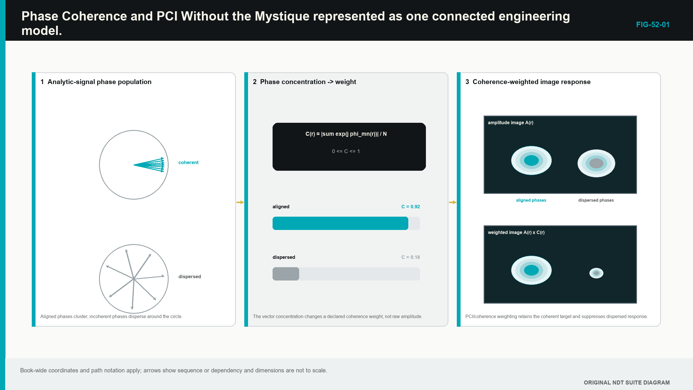
A compact reflector under a suitable path can produce phase agreement across many useful pairs; at a wrong pixel, predicted times miss the event and phases spread. Random independent noise often spreads as well. The same calculation can also align a backwall, cross-talk event or wedge reverberation when its timing matches the model.
Published work describes several phase and sign coherence approaches and shows why the output must be tied to its contributor rule, source signal and implementation rather than treated as a universal amplitude replacement. [R025] [R026] [R027] [R029]
52.3 Phase needs an oscillating source representation
An envelope shows magnitude around an RF packet; it does not retain the visible sign or complete cycle position. Phase-sensitive processing therefore starts from signed RF or another representation that preserves equivalent information.
Processing can form an analytic signal with two components; one is the observed RF waveform. The other is calculated in quarter-cycle relation under the declared method. Together they provide an envelope magnitude and an instantaneous phase angle.
The Level 2 learner needs the picture, not the transform derivation. Source bandwidth, sampling, filters, delay and the phase-extraction method remain controls; an envelope-only export cannot normally recreate original phase. A sign-only or one-bit acquisition can also discard amplitude irreversibly.
Polarity is a coarser indicator than full phase; a positive sample can be represented by +1 and a negative sample by -1. Sign-coherence methods can use that efficient reduction; they are related to, but not identical with, vector phase or phase-dispersion methods.
52.4 Four evidence conditions
The first condition is coherent signal. A real reflector supplies source waveforms above noise, the path model is accurate and many useful contributors align. Amplitude TFM and a coherence output can both respond.
The second is coherent non-defect response. A front surface, backwall, root, sidewall, electrical transient or wedge reverberation can repeat consistently. Coherence confirms agreement under the calculation; it does not name the cause.
The third is phase-inconsistent valid response. A smooth planar reflector may direct strong energy into only part of the aperture. Surface roughness, anisotropy, overlapping modes or model error can vary phase between pairs. An amplitude view may retain valid evidence while an all-aperture phase score becomes weak.
The fourth is incoherent noise or insufficient signal. Random noise tends to reduce agreement, but when the wanted waveform is also weak, its phase estimate becomes noise-controlled. Converting every small noisy sample into a unit arrow can create bounded speckle without useful acoustic support.
These four conditions replace the unsafe slogan that defects are coherent and noise is not. Some defects are poorly coherent under a selected aperture, and some benign events are highly coherent.
52.5 Understand the main failure routes
A wrong specimen velocity leaves a delay pattern that changes with depth and element position. A wrong wedge height or velocity shifts interface timing. A wrong surface profile changes entry points. A wrong mode can create a much larger timing error. Element-specific channel delay spreads phase even when the common time origin is correct.
Phase wraps every full cycle. A large timing error can occasionally produce local realignment after one or more complete cycles. Repeated peaks or false coherence can therefore appear. Coordinate movement, amplitude evidence and alternative path tests remain necessary.
Bandwidth matters because timing error represents different phase fractions at different frequency. A filter can change delay sensitivity and the scattering feature that dominates. Instantaneous phase is unstable at envelope zeros or overlapping packets. The implementation may use a window, band or threshold that is not visible in the final picture.
Noise is not always independent. Cross-talk tied to firing sequence, wedge ringing, repeated interface energy and multiplexing artefacts can be phase consistent. Real responses in coarse or directional material can vary from path to path. The technician checks raw amplitude, clipping, timing, coupling and aperture before interpreting the coherence display.
Contributor count also matters. A high value formed from five similar pairs does not carry the same support as one stable across hundreds of useful pair angles. Adding low-directivity or noise-only pairs can reduce a valid response. Where software exposes masks or counts, retain them with the image.
52.6 Separate three processing families
Amplitude TFM delays and combines signed waveform values. The display may show the RF result or an envelope. Source amplitude, gain, attenuation, transfer, aperture and normalisation remain part of the output.
Coherence-weighted amplitude imaging calculates a phase or sign agreement factor and uses it to modify an amplitude reconstruction. The result still contains amplitude information, but its scale has been changed by the weighting. Its units and thresholds belong to that documented implementation.
Amplitude-free PCI uses phase or sign agreement as the final pixel metric and discards amplitude from that route. It is not amplitude TFM with a different palette. Conventional decibel, percentage full-screen-height, distance-amplitude-correction or time-corrected-gain rules do not automatically apply.
All three can begin from the same full-waveform FMC acquisition. Another system may retain only sign or reduced phase data. That smaller record may be suitable for its defined PCI route but unable to produce ordinary amplitude TFM later. Data retention must state which case exists.
This terminology is functional, not vendor branding. A system provider may use a product name for one family or combine several operations. The controlled documentation and software version define the actual method.
52.7 Expect targets to look different
A small volumetric reflector can scatter across many angles and appear compact in both amplitude and coherence views. A side-drilled hole remains an extended cylinder with mode- and orientation-dependent response, so it is not a universal point target.
A crack tip or notch end can diffract weak energy over a broad angle range. Phase-only processing may increase its contrast relative to a strong broad interface. Tip-to-tip distance can support sizing only after both responses are demonstrated as physical tips under an authorised method.
A smooth planar face returns specular energy. Only a favourable portion of the aperture may receive it strongly. Amplitude TFM can show the face while PCI fragments or suppresses it. That suppression does not prove absence. It describes the interaction between reflector, aperture and phase metric.
Backwalls and component geometry can also be reduced in PCI. This can reveal nearby compact features, but it may hide the broad response used to monitor coupling, thickness or surface position. A parallel amplitude or dedicated coupling channel remains necessary when the technique depends on that evidence.
Two bright PCI points are not automatically the connected tips of one crack. Separate small reflectors, geometry or alternative modes can produce similar patterns. Path, movement, intermediate evidence and matched amplitude views are used together.
52.8 Matched-view comparison
The strongest comparison keeps source acquisition, encoded position, path, ROI, grid and aperture matched. One documented processing domain changes at a time. Where software prevents exact matching, every difference remains recorded.
For each response, compare physical coordinate and scan movement, source RF quality, useful aperture, fixed-scale amplitude morphology, fixed PCI scale, expected geometry, complementary paths, lift-and-replace repeatability and any authorised sizing points. The task must be named before one view is called better.
A weak diffracting tip may be clearer in PCI while a planar face or coupling boundary is clearer in amplitude TFM. That is complementary evidence, not a contest for the brightest screenshot. The plate below is reproduced under the Creative Commons Attribution 4.0 (CC BY 4.0) licence recorded in its credit block.
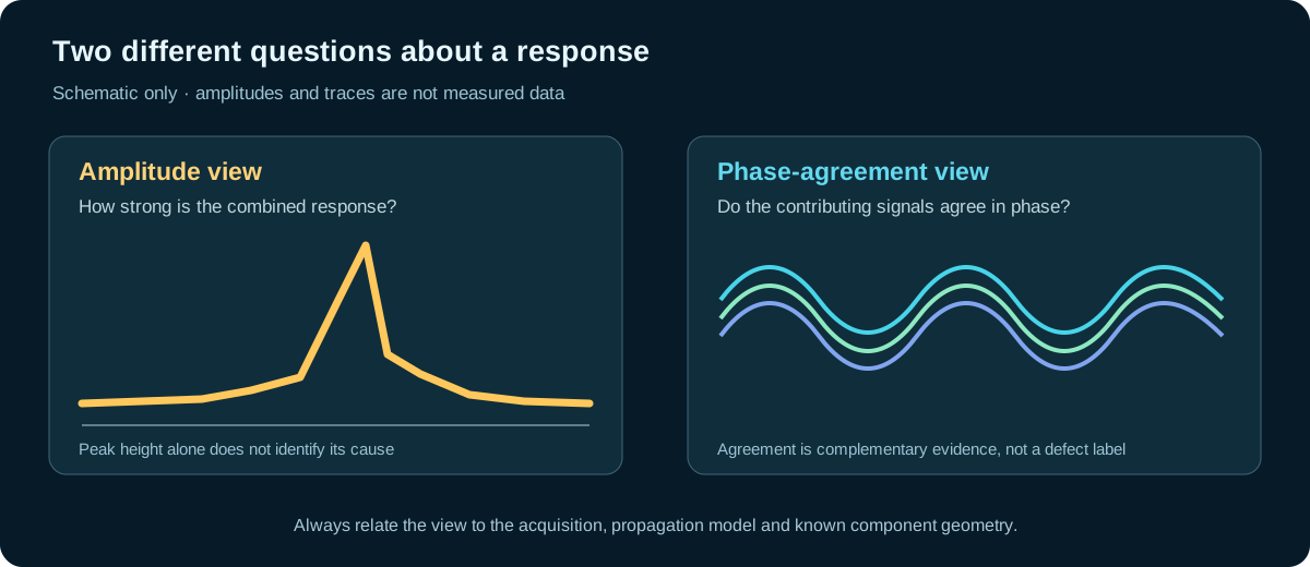
The published panels should be read as a matched processing comparison. They illustrate how image products can redistribute prominence; they do not provide a universal threshold, sizing rule or acceptance performance for another component.
52.9 A controlled comparison case
A teaching specimen contains one small volumetric target, one angled planar notch, defined upper and lower notch ends, and a known geometry boundary. A verified full-waveform FMC dataset is reconstructed first as amplitude TFM on a fixed reference scale. The same path, ROI, grid and aperture are then used for amplitude-free PCI under a documented software version and fixed display range.
The compact target appears in both domains. The planar notch face is strong in amplitude TFM but fragmented in PCI. Its ends form more compact PCI responses. The geometry boundary is reduced but not absent, while a fixed-time electrical transient remains coherent and produces a repeatable false feature.
Raw A-scans confirm that the compact PCI points have source signal above noise and below clipping. Probe lift-and-replace repeats their coordinates within the demonstrated tolerance. A second valid path supports the upper end but not the lower one, so the evidence package retains that asymmetry rather than connecting the points automatically.
The case shows all four Level 2 outcomes. PCI emphasises phase-consistent compact evidence, differs from amplitude TFM because it represents another quantity, fails on coherent non-defect and weak-source conditions, and does not by itself prove crack identity, size or acceptance.
| Worked example · Coherent and cancelling phase arrows WE-52-01 Given: Four phases are 0, 10, -10 and 5 degrees. A comparison set is 0, 90, 180 and 270 degrees. Find: The qualitative circular concentration of each set. Steps: The first four unit arrows point nearly together, so their average remains close to full length. The second set points in four equally spaced directions. Opposing components cancel exactly in the ideal calculation. Answer: The first set has high phase agreement; the second has zero resultant in the ideal equal-weight case. What it means in practice: Agreement depends on contributor quality and physical support. Coherent geometry can also give a long resultant, while noise-dominated arrows remain unreliable. Common mistake: Calling the first set a defect and the second set noise assigns physical cause from coherence alone. |
|---|
52.10 Gain, checks and sizing boundaries
An amplitude-free final scale may not need an amplitude reference curve. That limited statement does not mean the inspection needs no calibration or verification. Element and equipment health, time origin, wedge and component velocity, encoder, coordinates, paths, ROI, coupling, source dynamic range, target detection, location repeatability, software version and sizing performance still require control.
Gain determines how the analogue waveform enters the digitiser. Too little leaves useful signal in noise. Too much clips the waveform. The acceptable range is demonstrated on strong and weak relevant paths. A phase-only display cannot prove either condition from its colour alone.
Do not apply distance-amplitude correction, time-corrected gain, percentage full-screen-height thresholds, transfer corrections in decibels or amplitude-drop sizing directly to phase-only PCI. A validated tip-to-tip method or an implementation-specific contour may be used only when the procedure demonstrates and authorises it.
Detection improvement does not create acceptance criteria. If the governing rule is amplitude-based and no approved relationship exists, PCI can provide supplementary detection or characterisation evidence while evaluation remains with the authorised route.
52.11 Build an implementation profile
Record system, software and firmware version; probe, wedge and element range; acquisition architecture; retention of full RF amplitude; selected path and pair aperture; source range, sampling, gain and filters; documented coherence family; output scale and units; normalisation; threshold and smoothing; low-signal handling; contributor rules; ROI and grid; and export limitations.
If a parameter is proprietary or inaccessible, record that limitation. A black-box method can only be used inside the performance demonstrated for that controlled implementation. It should not be reverse-engineered through invented labels or assumed equivalent to a conceptual classroom equation.
The profile also states whether amplitude and PCI products can be recreated from the preserved source. If amplitude was discarded, that loss belongs in the evidence package.
52.12 Formal coherence signpost
Only after the physical picture is stable is a conceptual vector score useful. Replace every valid contributor by a unit arrow at its phase, average the arrows and take the length.
| (52.1) Conceptual unit-vector phase coherence · EQ-52-01 Where: C_v = conceptual vector-coherence score (dimensionless); K = included valid contributors (count); k = contributor index; phi_k = phase of contributor k (radians or consistently converted angle); exp(j phi_k) = unit phasor at that phase; j = square root of minus one (dimensionless) Model limits: phase comes from a declared analytic-signal method, low-support contributors follow a stated rule, and the equation is not asserted to reproduce a proprietary PCI algorithm |
|---|
Aligned unit arrows approach one. Evenly cancelling arrows approach zero. Because amplitude is removed, the score does not distinguish a strong supported waveform from a tiny noise-dominated waveform unless contributor rules do so separately.
Commercial methods can use sign, phase spread, in-phase and quadrature binarisation, weights, exponents, windows or sub-apertures. The equation is a teaching bridge, not a product definition. Chapter 59 compares the method families at Level 3. Chapters 69.16 and 72.2 to 72.8 develop phase estimation, circular statistics and advanced coherence at engineering depth.
In plain words
- Phase describes position within a repeating cycle and must be compared circularly.
- TFM delays align a possible common event before phase agreement is measured.
- Amplitude TFM, coherence-weighted imaging and amplitude-free PCI display different quantities.
- PCI can emphasise compact diffraction and suppress a broad planar response.
- Coherent geometry and electronics can also produce a strong phase response.
- Phase becomes unreliable when source signal is near noise or clipped.
- Matched views keep source, path, ROI, grid and aperture controlled during comparison.
- PCI does not supply amplitude units, universal sizing rules or acceptance criteria.
Key terms
- Phase agreement: similarity of cycle positions after declared delay alignment.
- Phasor: arrow representing one phase angle.
- Analytic signal: representation supplying waveform magnitude and phase.
- Coherence: calculated contributor agreement under stated rules.
- Coherence weighting: phase agreement used to modify amplitude reconstruction.
- Amplitude-free PCI: final metric based on phase or sign rather than echo amplitude.
- Contributor: one included pair sample supporting a pixel calculation.
Key relationships
- time shift/period -> phase fraction: the same delay produces a larger phase change at higher frequency.
- aligned phase arrows -> long average: agreement increases the conceptual coherence result.
- dispersed or opposing arrows -> cancellation: low resultant can reflect mismatch, noise or limited support.
- coherence != cause: phase agreement does not identify defect type or severity.
Common mix-ups
- High coherence is not proof of a discontinuity.
- Weak PCI response is not proof that a planar reflector is absent.
- Amplitude-free does not mean source-signal-quality-free.
- A coherence scale is not decibels or percentage full-screen height.
- A conceptual vector equation is not a definition of every commercial PCI product.
Bridge to Chapter 53
Chapter 52 showed what coherence can reveal and conceal. Chapter 53 turns those limits into proof and diagnosis. It separates dataset health, reconstruction plausibility and demonstrated application performance, then links common artefacts to the stage that can create them.
Sources and further study
- [R025]
- [R026]
- [R027]
- [R029]
Study and revision only. This is not an approved inspection procedure, acceptance criterion or qualification.