
CHAPTER 11 · Ultrasonics Level 2
Choosing the Probe and Transmission Arrangement
In this chapter · 20 sections
Why this matters
The same nominal frequency can produce very different results when probe construction, aperture, coupling or transmission path changes, so a probe suited to smooth plate may struggle on rough corrosion. A through-transmission arrangement may find a disturbed bond without providing depth, while an angle probe may reach a weld face that a straight beam cannot. Level 2 selection begins with the component and the information needed; catalogue specifications come after that physical problem has been understood.
What you already need
- Frequency, wavelength, pulse length and aperture affect the sound field.
- A short pulse helps separate echoes that are close in time.
- Coupling and surface condition affect the energy entering the component.
- A reflector responds most strongly from some directions and weakly from others.
- One-sided pulse-echo timing includes outward and return travel.
What you will learn
- Select a practical starting arrangement from target, access and surface conditions.
- Compare pulse-echo, pitch-catch and through-transmission evidence.
- Explain when single-element, dual-element, delay-line or immersion probes help.
- Connect frequency, aperture, focus and bandwidth to the target region.
- Calculate a simple water-path or two-leg travel time.
- Identify what must be checked after a probe, cable or wedge is substituted.
Words you will meet
- Pulse-echo: one-sided testing using a returning echo.
- Pitch-catch: separate transmitting and receiving probes.
- Through-transmission: a transmitter and receiver on opposite sides of a path.
- Delay line: material between the element and component that delays the first useful echo.
- Immersion: testing through a controlled liquid path.
- Focus: a region where the beam is made narrower or stronger.
- Substitution: replacing a system component with another one.
11.1 Start with the evidence the job needs
Probe selection can be reduced to one practical sentence:
Send a suitable wave along a usable path, make it interact with the target, and receive a feature that answers the job question.
The selection statement contains five linked choices: the component supplies material and geometry, while the target supplies likely depth, direction and size. The surface supplies access and coupling, and the required output may be a thickness, a location, a screening map or a supported size. The probe and arrangement must make all of those parts work together.
Consider three recurring cases in this part:
- A smooth plate needs a lamination survey and known back-wall response.
- A rough corroded wall needs reliable near-surface thickness readings.
- A butt weld needs sound directed toward fusion faces, root and weld volume.
The plate may suit a straight single-element pulse-echo probe, while rough corrosion often benefits from a dual-element arrangement with a short usable range. The weld normally needs an angle-beam path, but these are starting choices rather than guarantees. Reference evidence must show that the selected system works over the required region.
11.2 Pulse-echo, pitch-catch and through-transmission
Pulse-echo normally uses the same probe or aperture to send and receive. It needs access from one side and gives a return time related to a path. This makes it useful for thickness, reflector location and many weld examinations.
Pitch-catch uses separate transmitting and receiving apertures. Their paths can be arranged to receive directional energy that would miss a pulse-echo probe. Tandem arrangements are a special example used to interact with some near-vertical planar reflectors.
Through-transmission places a transmitter and receiver across the component or bond. The receiver measures energy that survives the path. A local drop can reveal a disturbed region. Depth is not automatic because the signal need not return from the condition.
The figure below compares the main arrangements. Notice which ones use one-sided access and which provide a returning path.
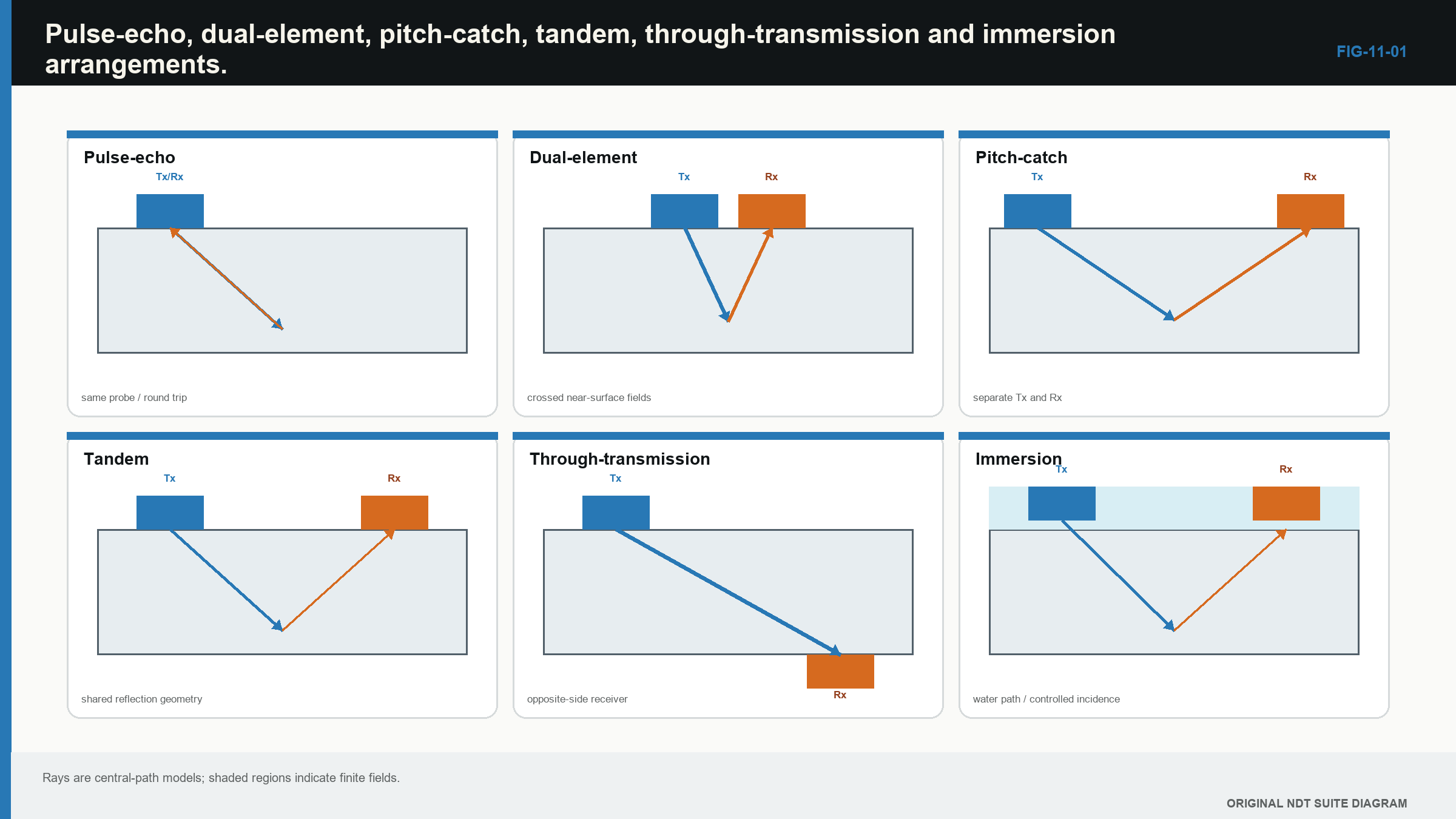
Notice that changing the arrangement changes both the available access and the measurement information.
| Worked example · Choose a starting arrangement for three jobs WE-11-01 Given: Case A needs wall thickness from one accessible side. Case B needs screening of a thin adhesive bond with access to both sides. Case C seeks a near-vertical planar reflector in a thick weld. Find: A reasonable starting arrangement for each case and the evidence it supplies. Steps: Match access and target direction to the path. For A, a returning back-wall time is needed. For B, a local change in transmitted energy may be useful. For C, separated or reflected angle-beam paths can interact with a near-vertical face. Answer: Use straight-beam or dual-element pulse-echo for A, through-transmission as a starting screen for B, and a geometry-designed tandem or suitable angle pulse-echo arrangement for C. What it means in practice: The arrangement follows the evidence need. Representative checks must still establish signal-to-noise, coverage and useful range. Common mistake: Choosing the arrangement with the highest screen echo without checking whether it can locate or size the target. |
|---|
11.3 Single-element and dual-element probes
A single-element probe normally uses one active element for transmit and receive. Its pulse-echo path is easy to picture. Pulse duration and receiver recovery can limit the shallow region.
A dual-element probe uses separate transmit and receive elements set at a small angle. Their fields cross below the surface. The separation helps reduce the early transmit disturbance and can improve measurements on rough, thin corrosion.
The crossed fields create depth-dependent sensitivity. At very shallow or deep positions, overlap can be weaker. The bent V-shaped path can also make the displayed thickness differ from a simple straight normal path. A dual-element correction may therefore be needed over its usable range.
For the corrosion case, compare repeatability on representative rough surfaces. A stable value on a polished block does not prove that a small pit will be measured correctly through scale or coating.
11.4 Delay-line and angle-beam probes
A delay line places a known material path between the active element and the component. It separates shallow component echoes from probe ringing, protects the element and can support elevated-temperature work when the materials are suitable.
The delay line also adds an interface, reverberations, wear and temperature-dependent time. Those effects become part of probe zero. A damaged or shortened delay line can shift every thickness result.
An angle-beam probe uses a wedge or another coupling arrangement to refract sound into the component. Wedge velocity, angle, wear and temperature affect the actual beam. The wedge also creates its own echoes and footprint.
For the weld case, the nominal label is only the starting point. Actual probe index and refracted angle must be checked. The selected path must reach the required weld region from a position the probe can physically occupy.
11.5 Contact and immersion arrangements
Contact testing is portable and direct. Its main practical variables are surface condition, couplant, hand pressure and probe rocking. A contoured or rough surface can make contact unstable.
Immersion testing uses a liquid path, usually water, between probe and component. The liquid gives stable coupling and supports mechanised position control. It can also provide stand-off for focusing and near-surface separation.
The water path adds an interface time. Temperature changes water velocity. Bubbles and surface motion disturb transmission. Curvature changes local incidence. Immersion removes the hand-held couplant film, but it does not remove acoustic geometry.
| Worked example · Calculate the front-surface time in immersion WE-11-02 Given: Water stand-off is 30.0 mm. Use a water velocity of 1,480 m/s. Find: The pulse-echo round-trip time to the component front surface. Steps: Round-trip water distance is 2 x 30.0 mm = 60.0 mm = 0.0600 m. t = distance/velocity = 0.0600 m / 1,480 m/s t = 40.5 x 10^-6 s Answer: The front-surface echo is expected at about 40.5 microseconds before other delays are included. What it means in practice: Internal component echoes begin after the water path and entry interaction. Temperature, bubbles or surface movement can shift the effective start. Common mistake: Treating the complete measured time as travel in the solid. |
|---|
11.6 Frequency, bandwidth and pulse choice
Probe frequency is a starting description, not the frequency that always reaches the reflector. A broadband 5 MHz probe contains a range of frequencies. Coarse material may remove much of the higher-frequency content before the pulse returns.
Higher frequency usually means shorter wavelength and potentially better separation of small features. It can also mean greater attenuation and structural noise. Lower frequency can improve penetration while giving a longer pulse and wider response.
Bandwidth describes the useful frequency range. Strong damping normally shortens ringing and broadens bandwidth, but can reduce peak sensitivity. A narrow-band probe can deliver a longer, stronger pulse while merging nearby echoes.
For the plate, weld and corrosion cases, use the lowest complexity that still meets the evidence need. Try candidate probes on representative paths and targets rather than selecting by nominal frequency alone.
11.7 Aperture, focus and surface fit
A larger aperture often produces a narrower far-field beam and greater sensitivity. It can have a longer near field and a larger contact footprint. That footprint may rock on a curved or rough surface.
A smaller aperture fits limited surfaces and spreads more widely. It may give lower local response but cover a broader angular region. The useful result depends on target depth and direction.
A focused probe narrows the field over a finite region, which can help separate small targets or improve a local scan while making stand-off and alignment more important. Focus should be compared with the full depth range, not only with the most convenient reference target.
The following figure organises these trade-offs. It is a study aid, not a universal rating chart.
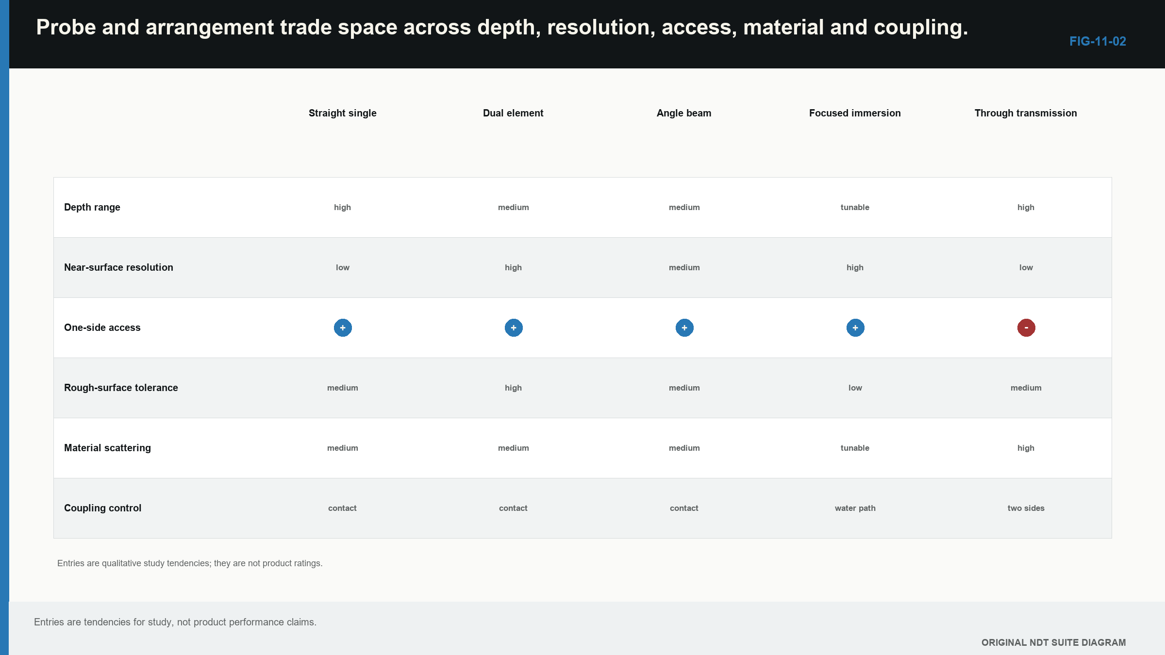
Notice that no probe sits at the best end of every trade-off, so the job objective must control the compromise.
11.8 Two-leg travel time in pitch-catch
With separate transmitter and receiver, the total time is the sum of the transmit and receive path times. Each segment can use a different mode or material.
In words:
total time = transmit path time + receive path time
| (11.1) Two-leg pitch-catch travel time · EQ-11-01 Where: t = predicted transit time (s); L_tx = transmit path length (m); L_rx = receive path length (m); c_tx and c_rx = speeds for the respective modes and segments (m/s) Model limits: declared specular/scattering point and straight homogeneous path segments | (11.1) Two-leg pitch-catch travel time · EQ-11-01 Where: t = predicted transit time (s); L_tx = transmit path length (m); L_rx = receive path length (m); c_tx and c_rx = speeds for the respective modes and segments (m/s) Model limits: declared specular/scattering point and straight homogeneous path segments |
|---|---|
| Worked example · Check a simple pitch-catch arrival WE-11-03 Given: A proposed response has a 60 mm transmit shear path and a 75 mm receive shear path. Use 3,230 m/s for both segments. Find: The predicted total travel time. Steps: Convert paths to metres and add their times. t = 0.060/3,230 + 0.075/3,230 t = 18.58 microseconds + 23.22 microseconds Answer: Predicted total time is 41.8 microseconds. What it means in practice: Agreement makes the proposed path plausible. Time alone may still allow more than one scattering position, so geometry and probe movement remain necessary. Common mistake: Dividing the combined path by two as if it were a one-probe pulse-echo thickness. |
11.9 Coupling and environmental limits
Coupling quality affects every contact arrangement. Too little couplant leaves air gaps. Excessive or changing film thickness can alter delay and response. Probe pressure and rocking change contact area.
High temperature changes wedge or delay-line velocity and can damage the probe. Buffer rods or intermittent contact protect the element but add paths and reflections. Immersion water temperature changes timing and refraction.
Environmental controls should match the consequence. For a simple plate survey, stable back-wall response may provide a useful coupling check. For amplitude comparison or fine sizing, repeated reference evidence may need tighter control.
11.10 Substitution is a technical change
Replacing a probe, cable or wedge can change zero, angle, bandwidth, sensitivity and beam position. Matching manufacturer and model numbers supports traceability. It does not prove that two worn or repaired items respond identically. [R010]
The check should follow the job. Thickness work depends strongly on zero, pulse shape and echo identity. Amplitude-drop sizing depends on beam profile and linear response. Angle-beam location depends on index and refracted angle. Near-surface work depends on recovery and usable range.
A useful substitution record states which properties were compared and over what path. It also states which parts were not shown to be equivalent.
The broader arrangement and probe-selection foundation remains consistent with the international UT training reference. [R001]
In plain words
- Start with the target, access, surface and required result.
- Pulse-echo gives a returning path and commonly supports one-sided location.
- Through-transmission detects a change in path energy but does not inherently give depth.
- Dual-element and delay-line probes can improve shallow access while adding their own path effects.
- Immersion improves coupling and position control but adds water-path geometry.
- Frequency, aperture and focus must suit the target region and material.
- A replacement probe or wedge is not equivalent until the properties needed by the job are checked.
Key terms
- Pulse-echo: transmit and receive using a returning acoustic path.
- Pitch-catch: separate transmitting and receiving apertures.
- Through-transmission: measurement of energy that passes through a component path.
- Delay line: an added probe path used for separation or protection.
- Immersion: coupling through a controlled liquid path.
- Focus: a finite region of narrowed or strengthened field.
- Substitution: replacement of a system component requiring task-linked checks.
Key relationships
- t = 2d/c gives round-trip time for a normal pulse-echo path.
- t = L_tx/c_tx + L_rx/c_rx adds transmit and receive segment times.
- Shorter wavelength can support finer separation, while material loss may reduce usable response.
Common mix-ups
- Through-transmission loss is not automatic discontinuity depth or type.
- Dual-element probes do not use one simple straight path at every thickness.
- A focus is a region, not a perfect point.
- Matching model numbers do not prove identical acoustic response.
- Non-contact or immersion arrangements are not free of geometry and coupling variables.
Bridge to Chapter 12
The probe and arrangement create the measurement path. Chapter 12 explains how that complete setup is connected to known time, position and amplitude references. It also separates calibration checks that are often bundled together under one convenient but dangerously vague word.
Sources and further study
- [R001]
- [R010]
Study and revision only. This is not an approved inspection procedure, acceptance criterion or qualification.