
CHAPTER 10 · Phased Array Ultrasonics Level 2
Electronic Scan Types and Focal-Law Planning
In this chapter · 14 sections
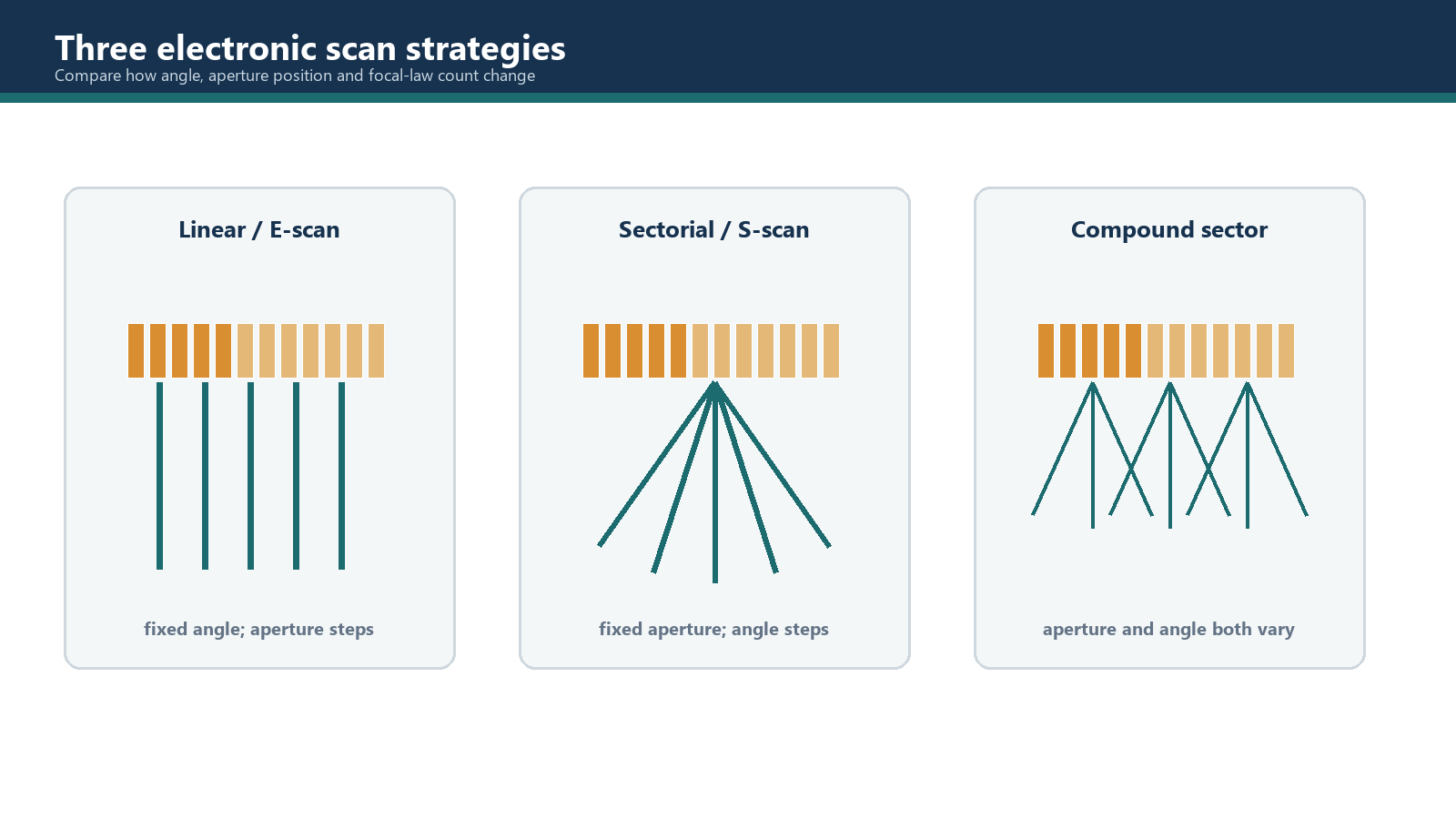
This chapter explains focal-law sequencing and its use in defensible coverage planning. It helps the learner document electronic scan types without confusing them with views, probe movement or encoding.
Learning outcomes
After completing this chapter, the learner should be able to:
- separate electronic beam sequencing from presentation, mechanical scan pattern and acquisition mode;
- explain multiplexing and identify the hardware resources needed by a law sequence;
- describe an electronic linear sequence using active aperture, aperture step, angle and focus;
- describe a sectorial or azimuthal sequence using aperture, angle limits and angle increment;
- explain compound and focus-sweep sequences without relying on a product-specific label;
- calculate integer law counts using declared endpoint and remainder conventions;
- compare scan types by coverage, beam behaviour, acquisition demand, calibration burden and data volume;
- identify when mechanical movement is still required despite electronic steering or aperture movement.
Key terms
Electronic sequence: An ordered set of focal laws executed by the acquisition system.
Multiplexing: Controlled connection of a limited set of pulser and receiver channels to different array elements or apertures over time.
Electronic linear sequence: A sequence in which a similar beam condition is moved along an array by changing the active aperture position.
Sectorial sequence: A sequence in which beam angle changes through a declared angular range, commonly using a fixed aperture position.
Azimuthal sequence: A term often used for a sectorial angle sequence in the active plane; the governing procedure must define the intended plane and angle convention.
Compound sequence: A sequence in which more than one beam parameter changes, such as both aperture position and angle.
Focus sweep: A sequence in which focal distance or depth changes while other declared beam parameters remain controlled.
Aperture step: The number of element positions by which the start of an active aperture moves between successive laws.
Angle increment: The change in programmed beam angle between successive laws in a sectorial sequence.
Law count: The number of distinct focal laws executed in a defined sequence or group.
Endpoint convention: The rule stating whether the first and last requested aperture positions or angles are included.
Group: A set of laws and acquisition settings assigned to one inspection function.
10.1 Four different meanings of scan
The word scan is often used so broadly that two people can discuss the same setup while meaning different things. A controlled technique separates four categories:
- Presentation: A-, B-, C-, D- or S-type view. This describes how data are displayed.
- Electronic sequencing: Linear, sectorial, compound or focus-sweep law order. This describes which beams are generated.
- Mechanical pattern: One-line, raster, spiral, helical or another physical probe path. This describes how the probe moves over the component.
- Acquisition mode: Manual or position-encoded collection. This describes how data are associated with position.
An S-type presentation is not, by itself, proof that the probe followed a sectorial electronic sequence; a software package may construct different views from stored data. Similarly, an electronic linear sequence does not mean that the operator moved the probe along a straight line. The technique record should state all four categories separately.
This chapter is concerned with electronic sequencing. Chapter 11 defines mechanical coordinates and patterns, while Chapter 12 deals with manual and encoded acquisition.
10.2 Multiplexing and channel resources
An array may contain more elements than an instrument can pulse or receive simultaneously. Multiplexing connects available channels to different element groups in a planned order. It selects participating elements; transmit and receive delays then create the beam. A complete law therefore needs element addresses as well as timing.
Before accepting a sequence, check total probe elements, element numbering, simultaneous pulser/receiver capacity, connector mapping, permitted aperture and address range, law/group limits and scheduling when several groups are active. Also establish whether transmit and receive apertures differ. A channel notation or model label is not a complete specification; the configured hardware and software determine what can be executed.
10.3 Electronic linear sequences
In a basic electronic linear sequence, the active aperture moves along the array while angle, mode, aperture size and nominal focus remain the same. If the first law uses elements 1 to 10 and the aperture step is two elements, the next law uses elements 3 to 12. The electronic movement creates a series of adjacent beam positions without physically moving the probe between those laws.
This sequence is also called an E-scan in some procedures and instruments. The label must be defined because linear scan is otherwise ambiguous: it could mean electronic aperture movement, a straight mechanical probe path or a line in a displayed image.
Electronic aperture movement can extend coverage across the length of the array and can provide a regular set of beam positions. It does not make the acoustic footprint equal to the element step. Adjacent beams overlap according to aperture, focus, wavelength, path and material response. The step should be selected from the required coverage and spatial sampling, then verified using appropriate reference targets.
The beam index point may move as the aperture moves. Position correction must use the index or exit information for each law rather than assigning every beam to the physical centre of the probe. This is especially important when the array is mounted on a wedge.
An electronic linear sequence is useful when a relatively constant beam angle is needed across a width. Examples include straight-beam mapping with a linear array and fixed-angle inspection from several adjacent virtual probe positions. It remains limited by the physical array length and by usable response near the first and last aperture positions. Full component coverage normally still requires mechanical movement.
10.4 Sectorial and azimuthal sequences
A basic sectorial sequence changes beam angle through a declared range. The aperture position and size are commonly held constant while the delay pattern changes for each angle. The resulting laws sample different directions from a similar region of the probe.
The setup must define:
- the angle reference, such as refracted angle from the surface normal in the component;
- wave mode;
- first and last programmed angles;
- angular increment and endpoint convention;
- aperture elements and effective aperture;
- focus definition for each law;
- wedge and material properties used by the law calculator.
The programmed angle list does not prove that every beam is equally useful. Element directivity, pitch-to-wavelength ratio, wedge transmission, critical angles, mode conversion, aperture projection, focus, attenuation, side lobes, grating lobes and reference-target response all affect the qualified range. Calibration can equalise selected reference responses; it cannot turn a weak or physically unsuitable beam into valid coverage.
Angular increment is a sampling decision. A smaller increment produces more laws and may show orientation changes more gradually, but it also consumes acquisition time and storage. It does not narrow the physical beam or guarantee detection between nominal central rays. Coverage must be based on characterised beam response and reflector orientation, not simply on how densely the software draws rays.
10.5 Compound and focus-sweep sequences
In this manual, compound means that more than one principal law parameter changes, such as angle at several aperture positions. Because equipment labels vary, record active elements, angle, mode, focus and execution order in a law table.
A focus sweep changes focal distance or depth. Each added transmit focus is normally another law, so focal-zone overlap, passive-plane response and law count must be assessed. Combining 9 aperture positions, 11 angles and 2 focal depths at every combination produces 198 beam conditions. Confirm the real firing sequence rather than assuming the display processes them without a timing or storage cost.
10.6 Counting linear-sequence laws
A law count must be an integer. For a uniform one-dimensional array using contiguous apertures, count the permitted aperture start positions rather than dividing element numbers and hoping that a fraction becomes a law.
N_laws = floor((N_total - N_active) / s) + 1
For this relation:
- N_total is the number of addressable elements available to the sequence;
- N_active is the number of adjacent elements in one active aperture;
- s is the aperture step in element positions and must be a positive integer;
- the first aperture is included;
- the floor operation discards any incomplete final step.
The relation assumes the same active count for every law, a contiguous uniform row, no missing or excluded elements inside the sequence and start at the first permitted element. If the sequence begins later or ends earlier, use the available address span rather than the probe's full element count.
Worked example 10.1 - linear law count with a remainder
Given: A 48-element array uses 10 adjacent elements per law. The start of the aperture advances by 3 elements. The first aperture starts at element 1.
Assumptions: All 48 elements are addressable, the apertures are contiguous, no element is excluded and a partial aperture is not permitted.
Calculation: The active aperture can move across 38 element-position intervals. Dividing 38 by the step of 3 gives 12 complete steps with a remainder of 2. Including the first position gives 13 laws.
Check: Aperture starts are elements 1, 4, 7 and so on through element 37. The last law uses elements 37 to 46. Elements 47 and 48 cannot support another 10-element aperture at the declared three-element step.
Conclusion: The answer is 13 laws, not 13.67 and not 14. A proposed final law must always be checked against the physical element addresses.
10.7 Counting sectorial-sequence laws
For a simple uniformly stepped sector, the count depends on the angular span, increment and endpoint convention.
N_laws = floor((theta_high - theta_low) / delta_theta) + 1
For this relation:
- theta_low and theta_high use the same declared angle reference and units;
- delta_theta is a positive angular increment;
- both endpoints are intended to be included when the increment divides the span exactly;
- the floor operation prevents a law beyond the upper limit when a remainder exists.
If the endpoint is mandatory but the increment does not divide the span, the setup designer must change the increment, change the limit or explicitly add a non-uniform final law. The software's rounding behaviour must not be assumed.
Worked example 10.2 - an inclusive sector
Given: A shear-wave group is planned from 34 degrees to 70 degrees in 3-degree increments, measured from the surface normal in the component.
Assumptions: The same aperture is used, both endpoints are included, angles are programmed exactly and no separate zero-degree or coupling law is part of this group.
Calculation: The angular span is 36 degrees. It contains 12 increments of 3 degrees. Including the first angle gives 13 laws.
Check: The sequence is 34, 37, 40 and so on to 70 degrees. Writing out the endpoints is a simple independent check of the arithmetic.
Conclusion: The group contains 13 laws. Whether all 13 are usable still requires beam and calibration evidence.
10.8 Selecting a sequence by inspection purpose
Compare every proposed sequence using the same controls:
- Beam behaviour: State which aperture, angle and focus parameters change; the law list has priority over the scan name.
- Coverage: Include beam dimensions, focal zones, access, skip paths, boundaries and expected discontinuity orientations. Central rays are planning aids, not proof.
- Resolution and sampling: Smaller law steps produce denser beam-centre sampling but do not narrow the physical beam.
- Timing and storage: More sequential laws normally reduce available complete-set rate and increase stored results. Confirm actual performance with the configured ranges, groups and processing.
- Verification: Establish timing, position and sensitivity evidence for every required beam or qualified grouping.
A compound sequence may reduce mechanical passes while increasing setup and review burden. Efficiency belongs to the complete controlled workflow, not merely to fewer probe movements.
10.9 Multigroup planning
Multigroup operation combines law sets for different inspection functions. For sequential operation, add every law required at one stored position. Groups of 13, 21 and 1 law require 35 pulse/receive cycles before considering averaging, pitch-catch firings or implementation-specific scheduling.
Verify each group's probe, wedge, material, mode, coordinates, range and PRF conditions. The complete setup must meet the encoded rate and storage requirements, and calibration must cover every required law or qualified grouping. Display update cannot be used as proof of the stored complete-set rate.
Field scenario - selecting sequences for a weld zone
Situation: A single-sided weld inspection needs several fusion-face orientations plus a fixed-angle check across a narrow adjacent zone. One guided mechanical pass is available.
Assumptions: Component geometry and expected orientations are known, and the wedge-array combination has been characterised.
Plan: Use a qualified sectorial group for orientation diversity and a fixed-angle electronic linear group for adjacent virtual probe positions. Add both law counts, prove the required encoded rate and map every beam to the same datum.
Verification: Demonstrate response at extreme qualified angles and end apertures, then confirm complete stored law sets and mechanical coverage beyond the finite array. Neither group alone satisfies both directional and lateral-placement objectives.
Common traps
- Calling a screen view an electronic scan type. Presentation and focal-law sequencing are different layers.
- Using "linear scan" without a qualifier. State electronic linear sequence, one-line mechanical path or displayed line explicitly.
- Treating electronic movement as full component coverage. The finite aperture and usable beam range still require a mechanical scan plan.
- Allowing a fractional law count. A focal law is either present or absent; write out the final address or angle.
- Adding one blindly to a division. The endpoint and floor convention must be defined first.
- Assuming all programmed sector angles are useful. Qualification depends on the complete acoustic system.
- Equating smaller steps with narrower beams. Step size controls sampling, not physical beam width.
- Ignoring multigroup timing. Every required firing belongs in the complete acquisition cycle.
- Relying on a product label for a compound sequence. Record the actual law table and changing parameters.
Chapter summary
Presentation, electronic sequencing, mechanical pattern and acquisition mode describe different layers of an inspection and must be recorded separately.
An electronic linear sequence moves an aperture while commonly maintaining its beam condition. A sectorial sequence varies angle from a commonly fixed aperture. Compound and focus-sweep sequences change additional parameters and can multiply law count rapidly.
Law counts require integer arithmetic, declared endpoints and a check of the last aperture or angle. More laws increase sampling and the timing, storage, calibration and review burden. Choose from qualified coverage and system capacity, not the scan name.
Study and revision only. This is not an approved inspection procedure, acceptance criterion or qualification.