
CHAPTER 1 · MT Level 2
The Level 2 Role and the Place of MT
In this chapter · 8 sections
Outcomes
After this chapter, the learner should be able to:
- explain what makes an examination non-destructive;
- state the material and discontinuity boundaries of MT;
- distinguish an indication, a discontinuity and a defect;
- compare MT with other common NDT methods at a screening level;
- identify decisions that require Level 2 judgement; and
- recognise when a procedure, code or Level 3 direction is required.
1.1 What MT is intended to do
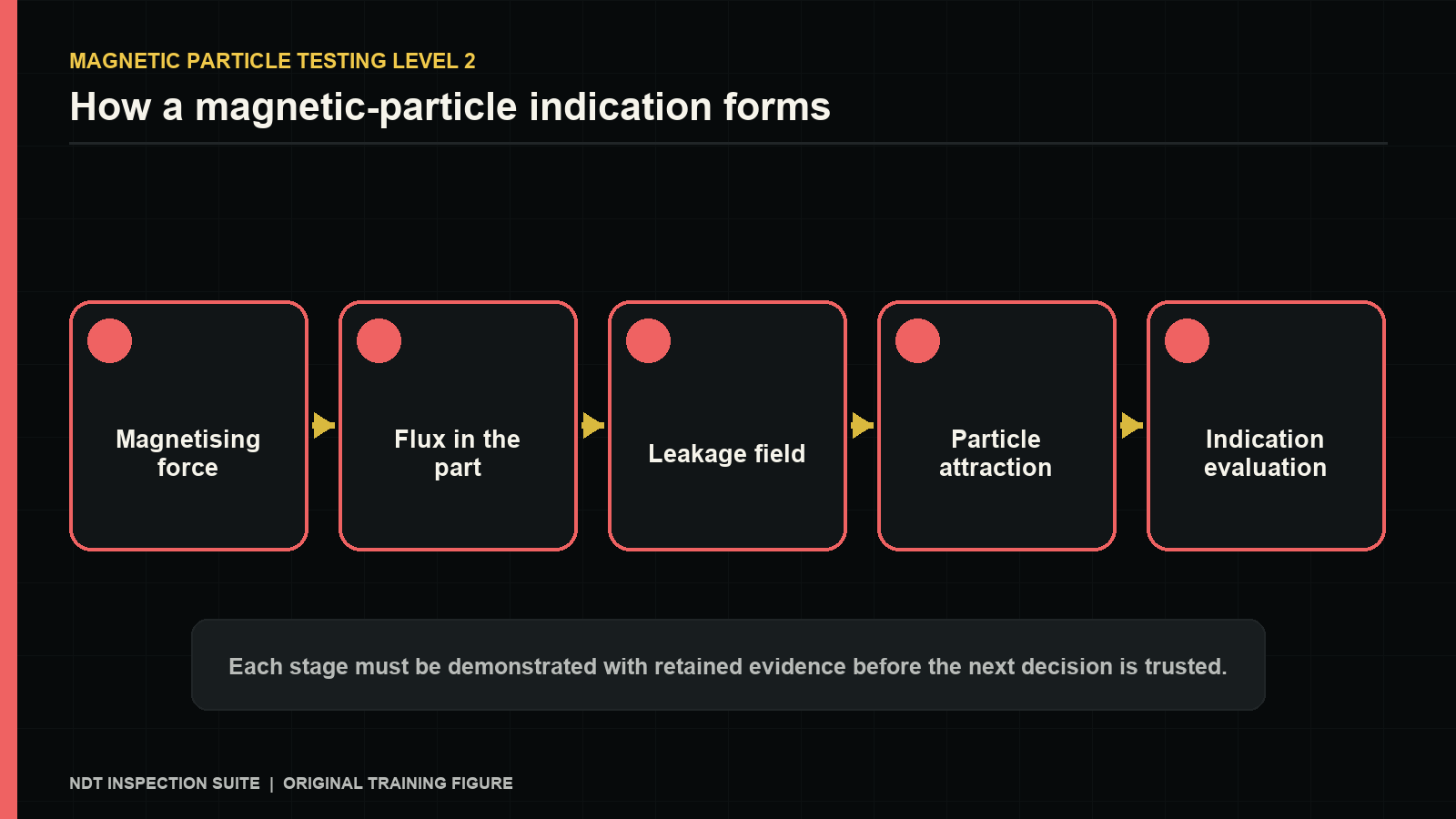
Magnetic particle testing is a surface examination method for ferromagnetic materials. The component is magnetised, and fine ferromagnetic particles are introduced at its surface. Where the magnetic path is disturbed, a leakage field can attract particles and create a visible indication.
The method is highly responsive to surface-breaking planar discontinuities and can reveal some near-surface discontinuities when the material, depth, orientation, current waveform and field strength are favourable. MT is not a volumetric survey of an entire section. It is also not applicable merely because a component conducts electricity; the part must respond ferromagnetically in the condition being examined.
Common candidate materials include many carbon and low-alloy steels, ferritic and martensitic stainless steels, iron, nickel and cobalt. Austenitic stainless steels, aluminium, copper, titanium and most non-ferrous alloys are outside normal MT scope. Material grade, heat treatment, weld metal and local microstructure can change the actual response, so identification must precede technique selection.
1.2 NDT method context
No NDT method answers every question. A Level 2 practitioner should understand why a method was selected and what remains unexamined.
| Method | Primary strength | Important boundary |
|---|---|---|
| Visual testing | Immediate surface and workmanship information | Requires access and adequate visibility |
| Penetrant testing | Surface-breaking discontinuities in many non-porous materials | Cannot reveal sealed near-surface conditions and requires a clean, open surface |
| Magnetic particle testing | Fast, sensitive examination of surface and favourable near-surface discontinuities in ferromagnetic material | Limited by material response and field orientation |
| Eddy current testing | Surface and near-surface electromagnetic response in conductive material | Signal interpretation depends strongly on geometry, conductivity and permeability |
| Ultrasonic testing | Internal reflectors and thickness through one-sided access in many materials | Coupling, geometry, orientation and acoustic properties control response |
| Radiographic testing | Through-thickness density variation with a permanent image | Radiation controls, access geometry and orientation affect capability |
MT can be more tolerant of a thin, qualified coating than penetrant testing, but coating thickness and condition can reduce sensitivity. It is usually quicker to apply on ferromagnetic welds than a multi-stage penetrant process. The trade-off is that MT cannot be transferred to an aluminium or austenitic stainless component simply because the geometry is similar.
1.3 The Level 2 decision chain
A competent Level 2 technician does more than energise a yoke. The role commonly includes:
- reviewing the job scope and controlling documents;
- confirming identity, material, temperature, surface state and access;
- selecting or applying an approved technique;
- setting and verifying equipment and media performance;
- establishing two or more effective field directions where required;
- examining, interpreting and classifying indications;
- evaluating against the stated acceptance criteria when authorised;
- recording limitations, deviations and results; and
- controlling demagnetisation, post-cleaning and release.
If the contract does not provide acceptance criteria, the technician may report indications and limitations but should not invent a rejection rule. If material identity, technique coverage or an anomalous response cannot be resolved, escalate it rather than turning uncertainty into a confident-looking report.
1.4 Indication, discontinuity and defect
An indication is evidence produced by the examination. It may be relevant, non-relevant or false. A discontinuity is an interruption in the normal structure or continuity of a component. A defect is a discontinuity that fails the applicable acceptance criteria. The terms are not interchangeable.
The sequence matters:
- observe the particle pattern;
- determine whether it comes from a leakage field or from contamination/application error;
- relate a relevant pattern to likely component condition;
- measure and record as required; and
- apply the specified acceptance criteria only after classification.
1.5 Practical: suitability gate
Begin with applicability. Confirm that the examination volume is ferromagnetic in its present condition and that the discontinuities of concern are at, or sufficiently near, an accessible surface. Confirm that preparation can expose the area without damaging it or concealing the condition being sought.
Next establish technique feasibility. Geometry and access must allow useful equipment placement, at least two effective field directions where required, controlled particle application and suitable viewing conditions. The proposed sequence must cover the stated examination area rather than merely produce a strong field at one convenient location.
Finally establish authority and control. An approved procedure, technique sheet and acceptance basis must be available, and the electrical, chemical, UV-A, temperature, component-security and access hazards must be controlled. If any answer is no, change the technique, restrict and report the coverage, or consult the responsible Level 3/client.
1.6 Common traps
- Treating every particle pattern as a crack.
- Calling a reportable indication a defect before applying acceptance criteria.
- Assuming all stainless steels are non-magnetic or all steels are equally permeable.
- Selecting MT from a drawing title without confirming the actual material.
- Copying a current value from another component without checking geometry and waveform.
- Treating certification training as authority to depart from a controlled procedure.
Chapter summary
MT is a targeted electromagnetic surface method. Its success begins with material confirmation, expected discontinuity orientation and a controlled decision chain. Level 2 competence is demonstrated through justified choices, verified performance and accurate reporting - not by the number on a current dial.
Study and revision only. This is not an approved inspection procedure, acceptance criterion or qualification.