
CHAPTER 13 · FMC / TFM / PCI Level 2
Artefacts, Failure Modes and Troubleshooting
In this chapter · 14 sections
Purpose
Advanced images can be persuasive when they are wrong. An error may be acquired into the raw data, introduced by an incorrect geometry or velocity model, produced by a real but unintended propagation path, amplified during reconstruction or made visually dominant by display processing. Troubleshooting therefore starts by classifying the evidence, not by dragging sliders until the screen looks calmer.
The Level 2 technician’s task is to preserve the original data, form competing hypotheses, run discriminating checks and make controlled changes one variable at a time. Reprocessing is valid only when the raw data support it and the resulting configuration remains authorised. Lost coupling, clipping, missing positions and insufficient recorded time usually require reacquisition.
Learning outcomes
After completing this chapter, the learner will be able to:
classify artefacts by acquisition, model, propagation, reconstruction, display or positioning source;
predict the image effects of common timing, velocity, geometry and channel errors;
test competing explanations using raw A-scans, matrix patterns and alternate views;
distinguish coherent geometry or electronics from discontinuity evidence;
troubleshoot one controlled variable at a time; and
decide whether evidence supports reprocessing, reacquisition or escalation.
Crossover map: familiar false calls in a larger evidence chain
| Familiar UT/PAUT issue | FMC/TFM/PCI manifestation | Discriminating evidence |
|---|---|---|
| Poor coupling or lift-off | Position-dependent loss, changed phase stability or missing frames across many pairs. | Coupling channel, raw-trace trend and repeat scan. |
| Dead element | Structured matrix row/column loss and image distortion. | Tx–Rx health map and per-channel check. |
| Wrong wedge delay or index | Common displacement or view-dependent misregistration. | Known targets and independent geometry measurement. |
| Mode conversion or multiple | Response placed by an unintended but coherent path. | Alternate path reconstruction and time/path drawing. |
| Side or grating lobe | Duplicate/off-axis response that changes with aperture or path. | Aperture sensitivity study and supporting A-scans. |
| Threshold or smoothing | Feature appears, joins or disappears without new raw evidence. | Fixed-scale before/after display comparison. |
| Encoder slip | Stretched, compressed, repeated or discontinuous along-scan features. | Stored position sequence and physical distance check. |
A six-source classification
Use a source classification before testing causes:
Acquisition: coupling, channel health, clipping, sampling, filtering, cross-talk, time range or missing data.
Geometry/model: velocity, wedge, element, surface, thickness, origin or encoder registration.
Propagation: unintended mode, reflection, multiple, conversion, lobe, reverberation, shadow or geometry echo.
Reconstruction: wrong path, aperture, pair set, ROI/grid, interpolation, weighting or normalisation.
Display: threshold, colour range, envelope, smoothing, resampling or hidden scaling.
Position/data governance: encoder slip, wrong scan file, mismatched setup, software version or incomplete transfer.
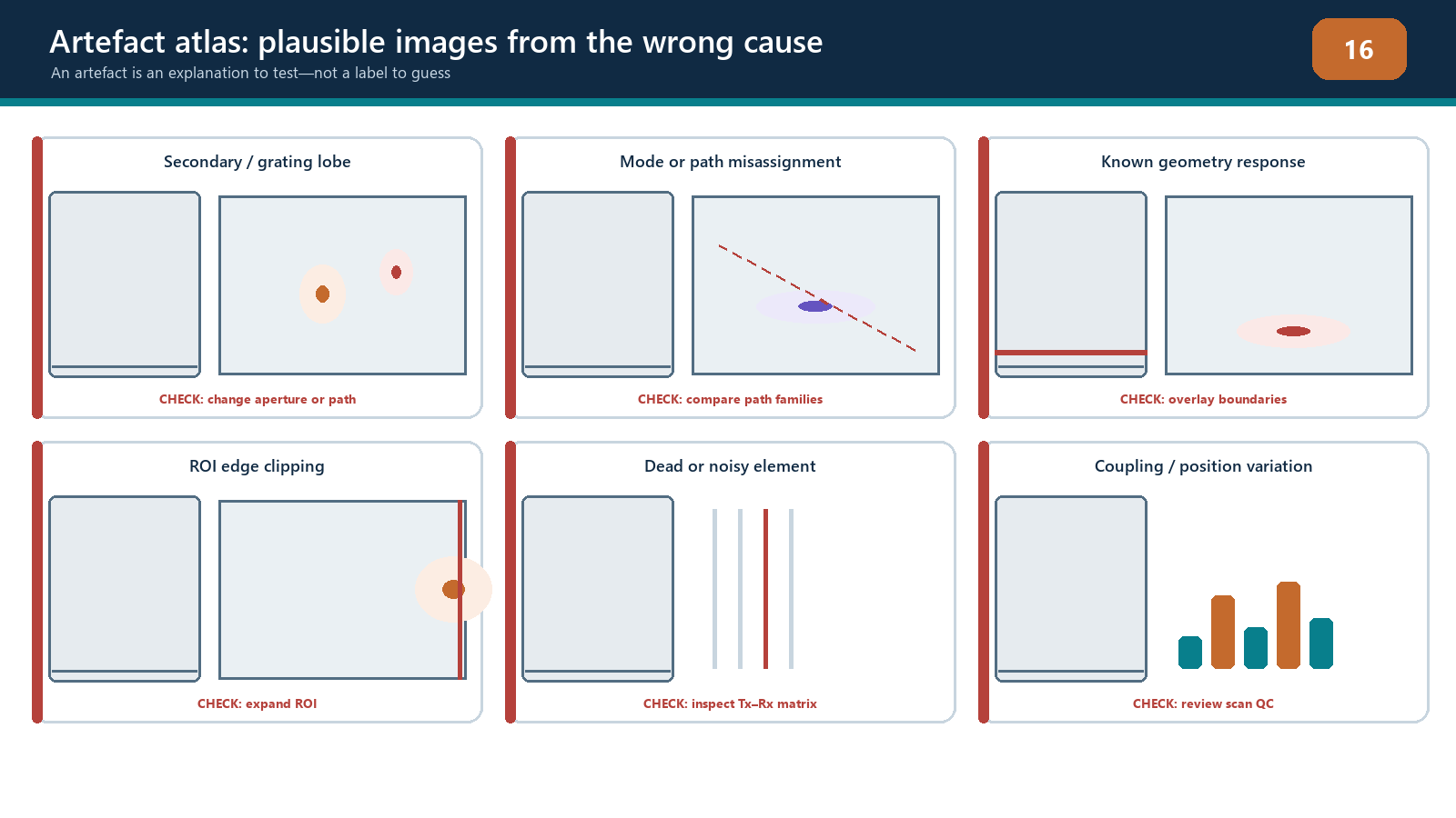
A symptom can have more than one source. A weak region may be poor coupling, attenuation, incorrect directivity assumptions or an over-aggressive threshold. A duplicated feature may be a multiple path, a lobe, repeated encoder positions or file assembly error. Record at least two plausible hypotheses before changing anything.
Acquisition failures
Inactive, noisy or inconsistent channels
Inspect the matrix as well as the image. A failed transmitter can mark a row; a failed receiver can mark a column; unstable connection can affect groups or change with cable movement. Relative timing error may produce phase dispersion and reduce coherence without making the channel visibly dead. Compare reference data acquired with the same controlled configuration.
An authorised channel exclusion may restore processing stability, but it changes the effective aperture and pair population. Its performance must be within the technique’s demonstrated limits. Silently excluding bad channels and continuing is not a repair.
Saturation, clipping and inadequate signal
Clipping flattens RF peaks and changes waveform phase. Phase-only processing does not recover the original waveform. Low gain or poor penetration can place samples in noise, where phase becomes unstable. Excessive analogue or digital filtering can alter bandwidth, timing and pulse shape. Compare raw RF, not only the reconstructed envelope or coherence display.
If clipping or inadequate signal is present in the retained acquisition, changing display gain cannot correct it. Reacquire after restoring a controlled linear range unless an authorised assessment demonstrates the affected data remain usable.
Coupling and motion
Coupling loss can affect many traces together and may resemble an attenuation zone or loss of coherence. Compare a dedicated coupling/backwall channel, raw pair amplitudes and position history. For a phase-only display that suppresses broad interfaces, independent coupling evidence is especially important.
Encoder dropout, repeated positions or slip can stretch, compress or duplicate indications along the scan axis. Review the stored position sequence and compare known physical start/end marks. Reconstructing again cannot recreate a position that was never acquired.
Model and registration errors
Wrong material velocity changes predicted travel times. A central response may remain convincing while deeper or off-centre responses displace and defocus. Wrong wedge delay or a common time-zero offset can produce a more uniform shift. Incorrect element pitch, wedge angle, probe index or surface origin can create lateral skew and view-dependent disagreement.
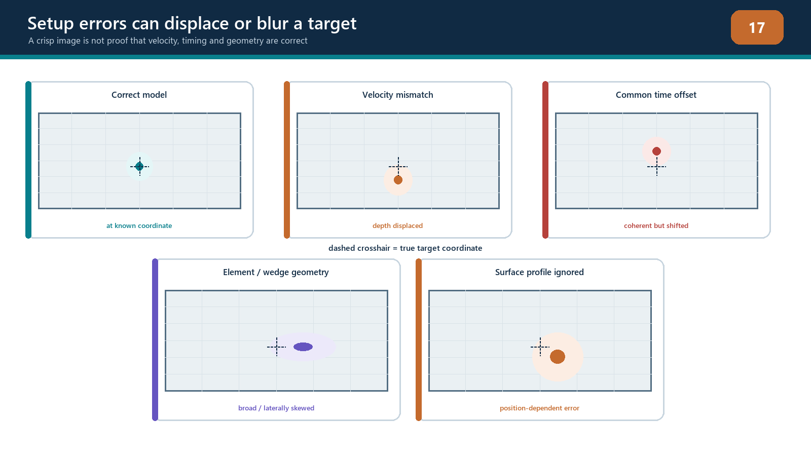
Use known reflectors at multiple coordinates to diagnose the pattern. Do not assume a universal displacement direction for every velocity error; it depends on path, geometry and coordinate convention. Change one input, predict the effect, then compare the result. If the response moves in an unrelated way, reconsider the hypothesis.
Curvature and surface profile deserve particular attention. A flat-surface model used on a curved or locally dressed surface changes interface points and refracted legs. The result can be position-dependent blur, wrong depth and reduced phase coherence. An ROI translation cannot repair the ray model.
Propagation and geometry artefacts
Real acoustic energy from the component can be irrelevant to the discontinuity question. Examples include:
wedge/interface echoes and ring-down;
cap, root, counterbore, backwall and attachment responses;
backwall multiples and reverberation;
mode-converted responses reconstructed as the wrong mode;
direct energy reconstructed using a skip path, or the reverse;
side/grating-lobe response from strong reflectors;
acoustic shadowing behind geometry or attenuation zones; and
reciprocal or alternative paths producing duplicate locations.
Draw the complete candidate path and calculate whether its time fits the raw response. Change to a complementary valid path, alter aperture within the demonstrated range, or inspect another scan position. A geometry response should follow the component geometry and repeat predictably. A lobe-related feature often changes relative position or strength with aperture. These are tests, not universal visual signatures.
Path degeneracy occurs when different routes have similar travel times over part of an ROI. The reconstruction can place coherent energy in a plausible but wrong location. One bright view cannot resolve the ambiguity. Use independent geometry, raw times and views whose paths differ meaningfully.
Reconstruction and display artefacts
An ROI boundary can clip a response, making it appear to terminate. A coarse grid can miss a peak or create position-dependent intensity. A very fine grid can produce a smooth display while consuming resources and encouraging over-precision. Excessive smoothing can join separate responses or broaden a feature. Interpolation and envelope choices can change peak location and shape.
Normalisation deserves special control. If every image is independently scaled so its maximum equals 100%, a noise-only view can appear as colourful as a high-SNR indication. A sensitivity map derived for another path or geometry can exaggerate weak regions or suppress real variation. Keep fixed-scale and unprocessed comparisons available.
Display thresholding does not remove noise from the dataset; it hides pixels. Lowering a threshold can reveal background texture and artefacts along with valid responses. Raising it can erase weak but relevant evidence. Detection thresholds and evaluation scales must come from the qualified technique.
PCI/coherence-specific traps
Coherent geometry, cross-talk and ring-down can produce high phase agreement. Conversely, a real smooth planar reflector may illuminate only part of the aperture and appear weak in a phase-only view. Low-magnitude samples can yield unstable phase, while a threshold or pair mask can change which contributors remain.
When an amplitude view and coherence view disagree, do not decide that one is “correct” by brightness. Check:
whether both use the same dataset, path, ROI and coordinates;
whether raw signals are linear and above noise;
whether the target is expected to be specular or diffracting;
whether aperture, band, masks and thresholds differ;
whether known geometry produces a coherent response; and
what the performance demonstration showed for representative targets.
The disagreement may be useful evidence. It is not permission to select the view that best supports a preferred conclusion.
Controlled diagnostic sequence
Freeze and copy the original dataset, setup and processing recipe.
Confirm file identity, component, position and software/version.
Describe the symptom in coordinates and image domain without naming a cause.
Inspect raw A-scans, matrix health, coupling and encoder history.
Draw the reported path and at least one competing path.
List two or more hypotheses across the six source classes.
Select one discriminating test and predict the result for each hypothesis.
Change one controlled variable or view at a time.
Compare with known-good reference data and representative targets.
Record the root cause, corrective action and affected data disposition.
If a change is outside the approved range, use it only as a diagnostic experiment on a copy and label the result non-reportable. Production reprocessing requires an authorised recipe and retained raw data sufficient for that route.
Reprocess, reacquire or escalate?
Reprocessing may be defensible when the raw acquisition is complete, linear, correctly positioned and retained with adequate time range, and the error is a controlled reconstruction input such as an authorised corrected velocity or ROI.
Reacquisition is normally required for clipping, insufficient signal, wrong analogue filtering, lost coupling, missing time range, missing channels beyond allowed limits, encoder gaps or the wrong physical scan path.
Escalation is required when the cause is unresolved, the correction changes an essential variable outside its range, a new path or algorithm is proposed, application capability is uncertain, or the result affects acceptance and no controlled disposition exists.
Practical 13 — Provoke and diagnose an artefact set
Aim
Diagnose a curated set containing both acquisition faults and intentionally incorrect reconstructions using a repeatable evidence process.
Resources
known-good FMC dataset and reference reconstruction;
variants containing channel loss, clipping, encoder dropout or coupling change;
controlled copies with wrong velocity, time offset, surface origin, path, ROI/grid and display settings;
access to raw pair A-scans, matrix view and position history; and
troubleshooting worksheet.
Method
Verify the known-good reference and freeze its display scale.
Review each unknown case without changing settings and describe the symptom.
Classify possible causes across acquisition, model, propagation, reconstruction, display and position.
List at least two hypotheses for each case.
Inspect raw RF, matrix, coupling and encoder evidence.
Draw the displayed path and one plausible competing route.
Choose one discriminating test, state the predicted outcomes, and perform it on a working copy.
Change only one variable at a time and preserve before/after evidence.
Identify the most supported root cause and whether the remedy is reprocessing, reacquisition or escalation.
Compare the diagnosis with the controlled answer key and explain any mismatch.
Evidence to retain
symptom and coordinate record;
hypothesis table and predicted discriminating results;
raw A-scan, matrix and encoder extracts;
fixed-scale before/after images;
path drawings;
root-cause and corrective-action statement; and
data-disposition decision with authority boundary.
Stop rules
Stop if the source dataset or processing revision is unknown; troubleshooting would overwrite the only copy; raw data needed for diagnosis are unavailable; more than one variable has been changed without a checkpoint; a production result is being altered with a non-approved recipe; or the remaining ambiguity could change acceptance. Preserve the evidence and escalate rather than forcing a tidy answer.
Common traps
Naming an artefact from appearance alone.
Adjusting velocity, ROI and threshold together.
Inspecting only diagonal A-scans or only the final image.
Assuming a bright coherent response must be a discontinuity.
Assuming a weak PCI response proves absence of a planar reflector.
Repairing encoder loss by interpolating invented positions.
Using per-image normalisation during comparison.
Treating diagnostic reprocessing as a reportable result.
Deleting the original recipe after finding a better-looking setting.
Continuing until one hypothesis “wins” despite contradictory evidence.
Chapter summary
Artefacts arise from acquisition, model, propagation, reconstruction, display and position/data-control sources. Similar symptoms can have different causes, and one fault can create several symptoms. Preserve the original data, describe the observation without prejudging it, form competing hypotheses and run a predicted one-variable test.
Reprocessing can correct only what the retained acquisition supports. It cannot replace clipped waveforms, lost coupling, missing positions or absent time range. Coherence processing can emphasise coherent geometry and suppress real planar response, so amplitude, raw-signal and multi-path evidence remain essential. Stop and escalate when the cause or authorised remedy cannot be defended.
Study and revision only. This is not an approved inspection procedure, acceptance criterion or qualification.