
CHAPTER 2 · Ultrasonics Level 1
Why Materials Carry Sound Differently
In this chapter · 18 sections
Why this matters
The same probe can produce a clean back-wall echo in fine-grained steel and a noisy, weak trace in a coarse casting. That difference is not the instrument being moody for sport. Sound travels by making the material move and resist that movement. Density, stiffness, grain structure, layers, temperature and manufacturing history all affect the result. This chapter gives a first-time learner a practical material picture before introducing the equations used to estimate wave speed.
What you already need
- A probe sends a mechanical pulse and receives returning sound.
- An A-scan response depends on the whole test arrangement.
- Basic square-root calculations are shown step by step.
What you will learn
- Explain why a material needs both mass and stiffness to carry a mechanical wave.
- Distinguish longitudinal and shear motion in simple language.
- Describe how grains, layers and manufacturing affect ultrasonic behaviour.
- Compare wavelength with the size of material features.
- Explain why stiffness and density both influence wave speed.
- Build a useful material description before selecting an ultrasonic approach.
Words you will meet
- Density: mass contained in a given volume.
- Stiffness: resistance to elastic deformation.
- Grain: a small crystal region inside a polycrystalline material.
- Scattering: redirection of sound by material variations or boundaries.
- Anisotropic: having properties that change with direction.
2.1 A wave needs mass and a restoring action
Push one end of a row of lightly connected objects. The first object moves, presses on the next and then tends to return. The objects do not travel to the far end as a group. The disturbance travels because each part has mass and interacts with its neighbour.
A solid behaves in a far more complicated way, but the simple picture contains two important ingredients. Its mass makes each small part resist a sudden change in motion. Its stiffness provides a restoring action that tends to return displaced material toward its original position. Together, these allow a mechanical disturbance to travel.
Ultrasonic displacements used in ordinary ultrasonic testing are extremely small. For a useful first model, the material returns to its original shape after the pulse passes. In the same model, doubling a small applied force doubles the small deformation. Open wave-equation teaching material connects this push-and-return response and density to longitudinal and shear-wave motion. [R004]
Real materials are not perfectly simple. They contain grains, phases, inclusions, pores, interfaces and residual stresses. Some absorb energy. Some scatter it. Some behave differently with direction. We keep the first model because it explains the main wave types and gives sensible speed estimates. Later chapters add complexity when the simple model is no longer good enough.
For now, keep one picture in mind: each small region moves a little, presses or pulls on its neighbour, and then tends to return. The disturbance travels while the material stays in place.
2.2 Compression, shear and simple stiffness
There are two simple ways to picture material movement. Squeezing or stretching changes a small region's length. Sliding one face sideways changes its shape. A material can resist these two movements by different amounts.
A longitudinal wave mainly moves particles back and forth along the direction in which the wave travels. The material repeatedly compresses and relaxes. A shear wave mainly moves particles across the travel direction, so the material repeatedly changes shape.
An ordinary liquid resists compression. It can therefore carry a pressure or longitudinal wave. It does not hold a sideways elastic shape, so it cannot carry an ordinary freely travelling bulk shear wave. A solid normally resists both compression and shape change and can carry both modes.
Stiffness and density work together. If two imaginary materials had the same density, the stiffer one would generally carry the comparable wave faster. If they had the same stiffness, the denser one would generally carry it more slowly. Real materials change both properties together, so neither stiffness nor density alone gives the answer.
At Level 1, the normal working input is an established or nominal velocity for the stated material and wave mode. The technician compares that input with a known sound path where the job requires it. A table value is a starting point, not proof of the exact component velocity.
This matters even when the component thickness has not changed. Imagine using a steel velocity while the probe is coupled to a thick acrylic block. The echo time belongs to acrylic, but the instrument converts it with the faster steel value. The displayed distance will be wrong. The extra digits on the screen do not rescue the wrong material choice.
The wave mode also belongs in the material description. A longitudinal wave and a shear wave can travel at different speeds in the same steel. Before entering a velocity, state the material and mode together, such as “longitudinal wave in fine-grained steel.” That short habit prevents a familiar number from being used on an unfamiliar path.
Step up preview - the formal elastic model
Later levels call the return-to-shape behaviour elastic and the resistance to a motion change inertia. They describe force per area as stress, relative deformation as strain, and different kinds of stiffness with elastic moduli. Those quantities can be combined with density to calculate ideal longitudinal and shear speeds. The full equations and modulus calculations are deliberately moved to Level 3 and Engineering Ultrasonics, after the physical difference between compression and shear is secure.
2.3 Grains and manufacturing history
Most engineering metals contain many small crystals called grains. Each grain has an ordered atomic pattern. Neighbouring grains can have different orientations. A pulse usually crosses a very large number of them.
When grains are fine and their orientations are well mixed, the component can often be treated as having the same average behaviour in every direction. That is an isotropic model. When stiffness or velocity changes with direction, the material is anisotropic. When properties change from place to place, it is heterogeneous. A material can be both anisotropic and heterogeneous.
Manufacturing controls much of this structure:
- Rolling can stretch grains and inclusions along the rolling direction.
- Forging can create grain flow around the product shape.
- Casting can produce coarse grains, segregation, shrinkage and pores.
- Weld solidification can produce long, directionally arranged grains.
- Heat treatment can change phase, grain size, residual stress and hardness.
- Additive manufacture can create structure linked to build direction and thermal history.
The structure affects two parts of an inspection. First, it changes how sound travels. Second, it changes which discontinuities and orientations are plausible. A rolled plate may contain flattened inclusions parallel to the surface. A weld may contain a planar lack-of-fusion condition along a fusion face. A casting may contain distributed porosity or shrinkage.
Materials knowledge therefore guides the acoustic hypothesis. Instead of searching for a generic “defect,” the technician considers what the manufacturing route could have created and how the selected wave might meet it.
2.4 Wavelength compared with material structure
The pulse has a length scale called wavelength, introduced fully in Chapter 3. For now, picture the distance between repeating parts of a wave. The relationship between this length and the material structure affects what the wave experiences.
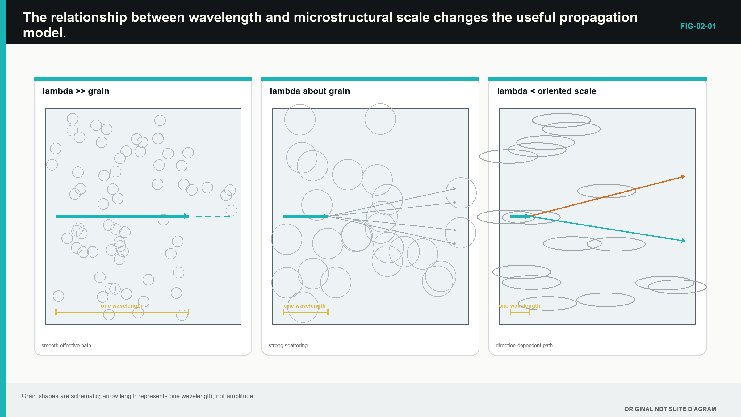
If wavelength is much larger than fine, randomly arranged grains, the pulse can average across many grains. A simple effective velocity may work well. When grain size becomes important compared with wavelength, more energy is redirected. This is scattering. Returns from many grains can appear as structural noise on the A-scan.
If the material has large organised grains, layers or fibres, direction also matters. The straight line predicted by a simple isotropic model may not match the direction in which most energy travels. Advanced composite-ultrasonic work distinguishes wavefront direction, energy direction and the scale over which material can be averaged. [R006]
The following figure compares three scales. Notice that “homogeneous” is not an absolute label. It describes whether the material variation is small enough to be averaged for the wavelength and measurement being used.
Scattering is not simply electrical noise. It is real acoustic interaction with the material. A measured drop in echo height can combine absorption, scattering, beam spreading, interface transmission and coupling variation. Calling every drop “material attenuation” hides these other causes. National Institute of Standards and Technology (NIST) material-characterisation work treats scattering and backscatter as responses linked to microstructure. [R009]
Higher frequency gives shorter wavelength in the same material. Short wavelength can help with fine detail, but it can also increase scattering and absorption. Lower frequency may pass through coarse material more effectively, though its ability to resolve close features is lower. Frequency choice is a trade, not a competition to select the biggest number on the probe case.
2.5 Different material families, different behaviour
Material names that sound similar can hide very different ultrasonic behaviour.
Fine-grained ferritic steel is often favourable for common bulk-wave examinations. Product form, welding and heat treatment still matter. An austenitic or nickel-alloy weld can be coarse and directionally structured. The beam may skew, split or produce heavy structural noise. Cast iron varies widely because graphite shape and matrix condition affect the path.
Aluminium has different density, speed and interface behaviour from steel. Polymers can absorb more sound and change strongly with temperature. Fibre composites contain layers and directionally arranged fibres. Guided and bulk waves in those materials require a model suited to their construction.
The phrase “the velocity of stainless steel” is therefore too broad for careful work. Fine-grained wrought austenitic plate, centrifugally cast pipe and austenitic weld metal can behave differently even when their chemistry is related. Useful descriptions include material family, product form, manufacturing route and direction.
A material change also affects likely responses. A planar inclusion aligned by rolling can reflect strongly toward a straight-beam probe. Distributed rounded pores may scatter energy in several directions. A fatigue crack may be very directional. The probe does not know the flaw name; it responds to the physical interaction.
2.6 Loss, temperature and material state
An ideal pulse would travel without changing. A real pulse loses height and can change shape. Part of its energy becomes heat through internal friction. Part is scattered away from the receiver. The beam spreads. Interfaces transmit only part of the incident energy. Coupling and reflector direction add further changes.
Some materials remove high-frequency content more strongly. The received pulse then becomes longer and lower in effective frequency as the path increases. A short pulse measured on a clean reference block may be longer after travelling through a thick coarse casting. That change reduces the ability to separate close echoes.
Polymers, adhesives and some composites can show strong dependence on frequency and temperature. Their stress and deformation do not remain perfectly in step. Level 3 and Engineering Ultrasonics describe this with frequency-dependent or complex stiffness. At Level 1, the practical lesson is that material loss can change both amplitude and pulse shape.
Temperature changes elastic stiffness, density and physical dimensions. A velocity selected at room temperature may not represent a hot component. Stress can also create small direction-dependent changes in speed. These effects are usually smaller than choosing the wrong wave type, but they matter in precision and specialised measurements.
Heat treatment, phase change, ageing and damage can alter response. This is why ultrasonics can sometimes support material characterisation. It is also why one ultrasonic value rarely proves one unique material condition. Several different changes can produce a similar velocity or attenuation change.
Step up preview - linking properties to speed
The formal model shows that wave speed rises with the relevant stiffness and falls with density when the other input is held still. Real temperature or material changes can affect stiffness, density and dimensions together. Calculating that combined behaviour is moved to later study; Level 1 uses a representative velocity and checks the resulting distance against known evidence.
2.7 From manufacturing route to probe path
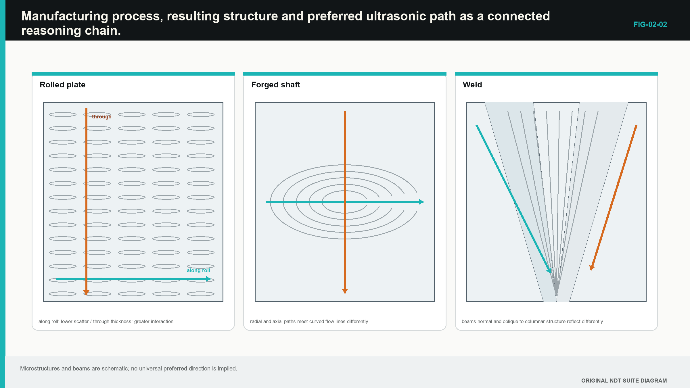
Consider a rolled plate containing elongated sulphide inclusions. Rolling suggests that many inclusions lie roughly parallel to the broad plate surface. A normal longitudinal beam approaches those planes close to square-on. It may produce strong early reflections and reduce the true back wall below them.
Now consider a forged shaft. Grain flow follows the shaped product. A radial beam and an axial beam travel across different structure. In a weld, heat flow can create long grains that change direction through the weld. A single nominal velocity may not represent every path.
The reasoning chain is:
- Identify how the component was made.
- Consider the structure and discontinuities that route can create.
- Consider their likely direction and location.
- Choose a wave and probe direction that can reach them.
- Check whether the material allows enough useful signal to return.
The following figure shows this chain for rolled plate, forged material and weld metal. It does not prescribe one universal direction. It shows why the direction must be reasoned from the component.
A reference coupon should represent the important material behaviour. A fine-grained coupon from the same named alloy may not represent a coarse weld or textured forging. Similar chemistry does not guarantee similar propagation.
2.8 Describing the material before testing
A useful material description contains the facts that can affect the sound path and likely target. It may include:
- material family and grade when known;
- product form, such as plate, pipe, forging, casting or weld;
- manufacturing route and heat treatment;
- grain, inclusion, fibre or ply direction where relevant;
- temperature and important stress state;
- coating, cladding, surfaces and curvature;
- service history and expected damage mechanisms.
Not every field needs a laboratory number. The purpose is to decide which variables could change wave speed, loss, scattering, direction and target response.
At one scale, many small random grains may be represented by an average velocity plus a background noise level. At another scale, a large layer, weld region or organised texture must be modelled separately. Engineering Ultrasonics calls the averaging region a representative volume and can describe loss with complex stiffness. Those formal tools are deliberately postponed until the physical picture is secure.
The simplest model that answers the job is usually the best starting point. A single established velocity may be adequate for thickness in uniform fine-grained plate. It may be inadequate for a dissimilar-metal weld. The model is useful when its assumptions match the component closely enough for the required decision.
Material characterisation studies use velocity, attenuation and backscatter because they respond differently to structure. [R009] The result is rarely unique. A change in one ultrasonic quantity should be combined with manufacturing knowledge, reference evidence and other measurements before it is assigned one material cause.
In plain words
- A mechanical wave needs material mass and an elastic restoring action.
- Longitudinal motion is mainly along the travel direction; shear motion is mainly across it.
- Stiffness and density together control wave-speed scale.
- Grains, phases, pores, inclusions, layers and fibres can scatter or redirect sound.
- Manufacturing history affects both propagation and the kinds of discontinuity that may be present.
- Higher frequency can improve fine detail but can also increase material loss and noise.
- Temperature, material condition and direction can change velocity.
- A simple material model is useful only inside the conditions it represents.
Key terms
- Density: mass per unit volume.
- Stiffness: resistance to elastic deformation.
- Grain: one crystal region inside a polycrystalline material.
- Scattering: sound redirected by material variation or a boundary.
- Isotropic: represented as having the same properties in every direction.
- Anisotropic: having properties that depend on direction.
Key relationships
- A material needs inertia and an elastic restoring action to carry a mechanical wave.
- Greater relevant stiffness tends to raise wave speed when density is unchanged.
- Greater density tends to lower wave speed when stiffness is unchanged.
- Longitudinal and shear waves use different material resistance and therefore have different speeds.
Common mix-ups
- Density alone does not determine velocity.
- Electrical noise and structural noise do not have the same cause.
- Higher frequency is not automatically better.
- One alloy name does not guarantee one velocity in every product form and direction.
- An average material model does not erase real grains, layers or weld structure.
Bridge to Chapter 3
This chapter explained why a material can carry a disturbance and why different materials change it. Chapter 3 follows the disturbance itself. It introduces cycles, frequency, wavelength, pulse length, travel time and the different ways particles move.
Sources and further study
- [R004]
- [R006]
- [R009]
Study and revision only. This is not an approved inspection procedure, acceptance criterion or qualification.