
CHAPTER 9 · Phased Array Ultrasonics Level 2
Beam Artefacts, Bandwidth and Damping
In this chapter · 14 sections
Learning outcomes
After completing this chapter, the learner should be able to:
- distinguish the main lobe, side lobes and grating lobes;
- explain why pitch, rather than element width, controls periodic spatial sampling;
- describe how steering and wavelength alter grating-lobe risk;
- explain the benefits and costs of amplitude apodisation;
- relate damping, pulse length, bandwidth and quality factor correctly;
- calculate absolute bandwidth and compare quality factor from declared -dB frequency limits;
- explain why broadband operation does not prevent grating lobes;
- identify common beam or system responses that can imitate relevant indications;
- select a bandwidth class only after considering material, path, target and resolution requirements.
Key terms
Main lobe: Intended dominant part of the formed beam.
Side lobe: Secondary maximum caused by the finite aperture and its amplitude/phase distribution, normally adjacent to the main lobe.
Grating lobe: Additional strong beam produced by periodic spatial sampling when pitch, wavelength and steering geometry permit coherent reinforcement in another direction.
Apodisation: Intentional amplitude weighting across an aperture to change the beam pattern, commonly to reduce side-lobe level.
Ring-down: Continued vibration after excitation, producing a longer time-domain pulse.
Bandwidth: Frequency range between declared lower and upper response limits, measured at a stated amplitude drop.
Quality factor, Q: Measure of resonant sharpness commonly related to centre frequency divided by bandwidth under a stated definition.
Cross-talk: Unwanted electrical or mechanical transfer between channels or elements.
9.1 The beam contains more than a centre line
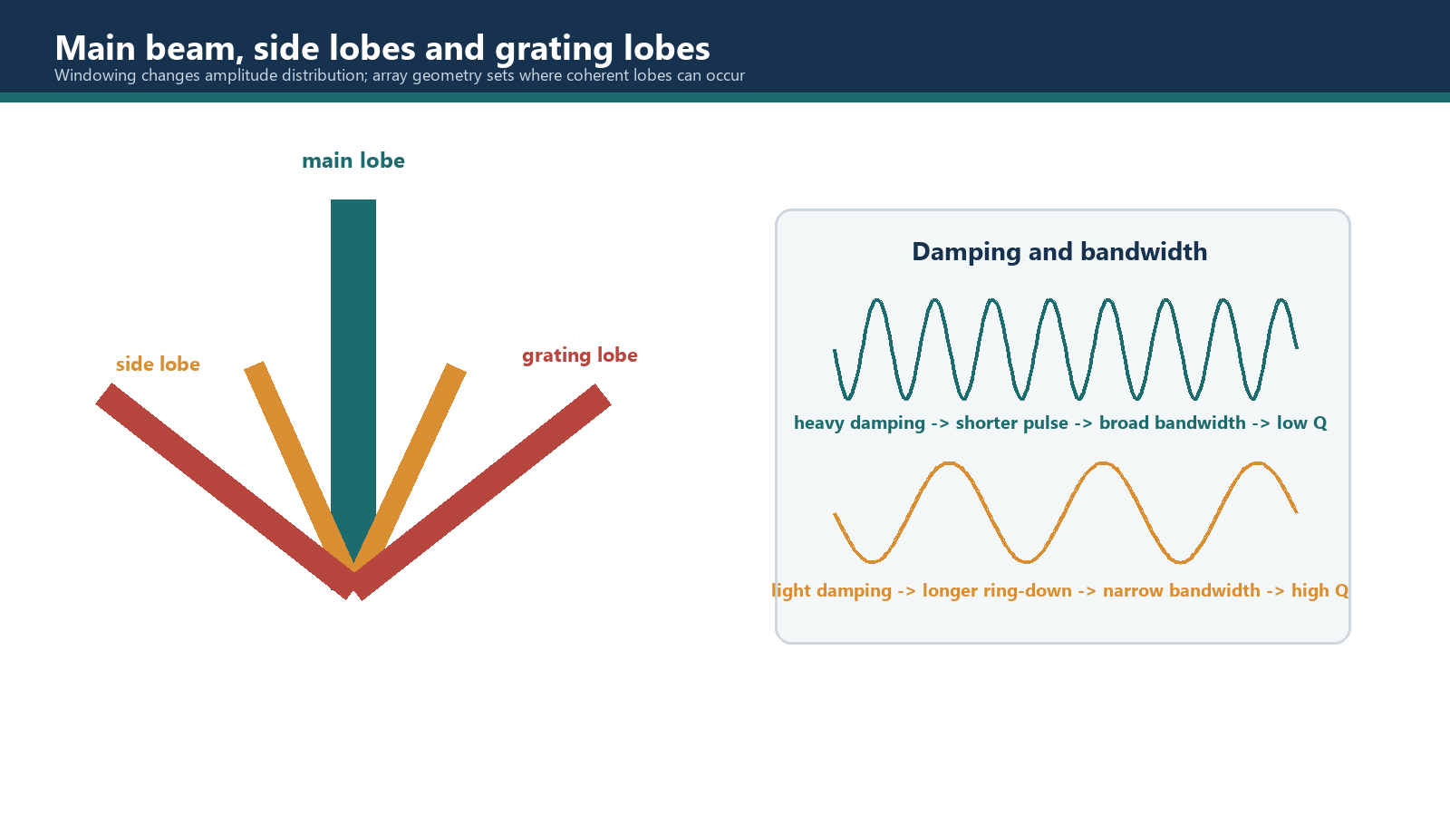
A focal-law display usually emphasises the nominal beam direction. The actual field contains a main lobe, side lobes, possible grating lobes and lower-level energy produced by the wedge, component boundaries and mode conversion. Any of these can interact with geometry or a reflector.
The main lobe is the intended region of strongest constructive interference. Its angle and focus are the design target, although measured maximum response may shift because of interfaces, material, curvature or an inaccurate model.
Side lobes arise because an aperture has finite size and a particular amplitude distribution. They are usually lower than the main lobe but can still produce responses from strong geometry outside the nominal beam. Side-lobe level and main-lobe width are linked through aperture weighting.
Grating lobes are not simply large side lobes. They arise when a regularly spaced array can satisfy coherent phase conditions in more than one direction. They may approach main-lobe strength and create convincing off-axis responses. Their existence is controlled principally by pitch relative to wavelength and the steering geometry.
9.2 Pitch, width and wavelength
The array samples an acoustic wavefront at the element centres. Pitch is therefore the relevant spacing for periodic spatial sampling. Element width influences the directivity envelope of each element, but replacing pitch with width in a grating-lobe condition changes the physics.
For a fixed pitch, increasing frequency shortens wavelength and increases the pitch-to-wavelength ratio. This can make unwanted spatial orders more likely or move them into a propagating region. Steering also changes the phase progression across the aperture, so a relation derived for an unsteered beam cannot be applied unchanged to a steered beam.
Assess pitch / wavelength together with steering angle using a validated array model
Because angle signs and reference axes differ between coordinate systems, a grating-lobe calculation is meaningful only when it defines:
- the steering-angle and lobe-angle reference;
- the sign convention;
- wavelength in the relevant medium and mode;
- pitch in the steered array direction;
- the integer spatial order;
- the condition under which a real propagating solution exists.
The familiar unsteered form is only a special case. For steered laws, use a validated array model whose coordinate convention matches the setup. A calculated angle is also not the complete acceptance test: element directivity, wedge transmission, aperture weighting, material attenuation and sensitivity determine whether the lobe is significant in practice.
9.3 Apodisation
Uniform excitation gives every active element the same nominal amplitude. Apodisation reduces amplitude toward the aperture edges or applies another controlled weighting pattern. This can lower side-lobe amplitude because the aperture changes more gradually at its boundaries.
The benefit has costs. Reducing edge contribution normally broadens the main lobe, lowers peak sensitivity and changes the effective aperture. The exact result depends on the weighting function, steering, focus and whether weighting is applied on transmit, receive or both.
Apodisation is therefore a trade-off, not a clean-up filter that removes every unwanted beam. It does not correct an unsuitable pitch or guarantee the absence of grating lobes. Any selected weighting should be included in modelling, reference-block verification and the saved setup.
9.4 Pulse length, damping and bandwidth
A transducer and its backing behave as a resonant system. If vibration is lightly damped, it continues for more cycles after excitation. The pulse has longer ring-down, a narrower frequency spectrum and a higher Q. If vibration is heavily damped, it stops sooner. The pulse is shorter, the spectrum is broader and Q is lower.
The correct relationships are:
- heavy damping -> short pulse -> broad bandwidth -> low Q;
- light damping -> long pulse -> narrow bandwidth -> high Q.
The relationships are reciprocal: longer ring-down narrows the spectrum and raises Q, while stronger damping shortens the pulse, broadens the spectrum and lowers Q.
A shorter pulse can improve axial resolution and near-surface separation. A longer resonant pulse can provide useful sensitivity in some low-attenuation or resonance-based applications, but it reduces separation of close echoes. Actual performance also includes matching layers, cable, wedge, couplant, material and receiver bandwidth.
Percentage categories such as "light," "medium" or "heavy" damping should not be assigned universal numerical bands without a defined measurement method and source. The measured spectrum and time trace are better evidence.
9.5 Measuring bandwidth and Q
Bandwidth must state the amplitude-drop level used to select the lower and upper frequencies. A -6 dB bandwidth is not numerically interchangeable with a -3 dB bandwidth.
Bandwidth = f_high - f_low
Absolute bandwidth is the upper limit minus the lower limit. Fractional bandwidth compares that width with a declared centre frequency and is normally expressed as a percentage. The centre-frequency definition and measurement method must be controlled.
Q = f_c / (f_high - f_low)
Q is commonly calculated as centre frequency divided by absolute bandwidth. A high value describes a narrow resonant response; a low value describes a broad response. Probe specifications, system checks and comparisons must use the same drop level and centre-frequency convention.
Do not confuse bandwidth with centre frequency. Bandwidth is the difference between the upper and lower limit frequencies; their arithmetic mean is one possible definition of centre frequency.
9.6 Broadband operation and grating lobes
A broadband pulse contains a range of frequencies. Each frequency has its own wavelength and therefore its own pitch-to-wavelength ratio and lobe directions. Summing a spectrum can spread lobe energy across angle and time, sometimes reducing the coherent prominence of one narrowband lobe. It does not remove the spatial-sampling condition.
It is unsafe to claim that broadband operation prevents grating lobes. The high-frequency portion of a broad spectrum has a shorter wavelength and may have a less favourable pitch-to-wavelength ratio. The correct control is to evaluate array pitch, complete spectrum, steering range, aperture, directivity and measured beam response together.
9.7 Selecting a frequency response
Broadband and narrowband probes are tools, not quality grades.
A broadband, well-damped response suits short pulses, axial separation and near-surface work, but its high-frequency energy may attenuate strongly in difficult material.
A narrowband, lightly damped response can provide sustained response around one frequency, but its longer pulse can obscure close or early echoes.
A medium-band design is a compromise, but the label still requires a measured spectrum.
Selection should consider material grain and attenuation, path length, expected reflector size and orientation, axial-resolution need, surface proximity, wedge transmission, required steering and the bandwidth of the complete instrument-probe system.
9.8 Other misleading responses
Not every off-axis or repeated response is a lobe. Alternatives include wedge/interface echoes, mode conversion, component geometry, reverberation, cross-talk, channel faults, saturation, filtering and encoded-position error.
Test a suspected artefact by changing one controlled variable at a time. A relevant indication should move consistently and corroborate across suitable views; an artefact often follows the wedge, boundary, channel or processing choice.
Worked example 1 - width is not pitch
Given: A uniform array has element width 0.50 mm and kerf 0.10 mm.
Assumptions: The kerf is uniform and pitch is measured centre to centre.
Calculation: Pitch is 0.50 + 0.10 = 0.60 mm.
Interpretation: Use 0.60 mm, not 0.50 mm, in a spatial-sampling or grating-lobe assessment. Use the 0.50 mm element width when assessing individual-element directivity. The two values describe different effects.
Worked example 2 - comparing bandwidth and Q
Probe A: Centre frequency 5.0 MHz; -6 dB limits 3.5 and 6.5 MHz.
Probe B: Centre frequency 5.0 MHz; -6 dB limits 4.7 and 5.3 MHz.
Assumptions: Both spectra were measured using the same method, load, drop level and centre-frequency convention. Values describe the measured system under those conditions.
Probe A calculation: Absolute bandwidth is 6.5 - 3.5 = 3.0 MHz. Q is 5.0 / 3.0 = 1.67 approximately.
Probe B calculation: Absolute bandwidth is 5.3 - 4.7 = 0.6 MHz. Q is 5.0 / 0.6 = 8.33 approximately.
Conclusion: Probe A is broader band and lower Q. Probe B is narrower band and higher Q. The values do not by themselves decide which probe is suitable; the inspection objective and material decide that.
Common traps
- Calling every secondary maximum a grating lobe. Side and grating lobes have different causes.
- Using element width in place of pitch. Width controls element directivity; pitch controls spatial sampling.
- Applying an unsteered lobe equation to a steered law. Steering angle and sign convention must be included.
- Assuming apodisation removes grating lobes. It mainly trades side-lobe level against main-lobe width and sensitivity.
- Reversing the Q relationship. Light damping is narrowband/high-Q; heavy damping is broadband/low-Q.
- Calculating bandwidth as the average of limit frequencies. Bandwidth is their difference.
- Claiming broadband operation prevents grating lobes. It can smear prominence but cannot cancel the underlying spatial geometry.
- Diagnosing from one static view. Geometry, mode conversion, cross-talk and processing must be tested as alternative causes.
Chapter summary
The intended beam is accompanied by side lobes and, under unsuitable spatial-sampling conditions, grating lobes. Side lobes arise from the finite aperture and weighting. Grating lobes arise when periodic element spacing allows coherent reinforcement in another direction. Pitch, wavelength and steering geometry control the condition; element width controls the individual-element directivity envelope.
Apodisation can reduce side-lobe level, but generally broadens the main lobe and reduces peak sensitivity. It does not repair unsuitable pitch. Broadband energy may smear lobe prominence but does not prevent grating lobes.
Heavy damping produces a short pulse, broad bandwidth and low Q. Light damping produces longer ring-down, narrow bandwidth and high Q. Bandwidth is the difference between declared upper and lower limit frequencies, while Q is commonly centre frequency divided by bandwidth. Probe selection must consider the complete material, path, target, resolution and steering problem.
Study and revision only. This is not an approved inspection procedure, acceptance criterion or qualification.