
CHAPTER 12 · FMC / TFM / PCI Level 2
Calibration, Verification and Performance Demonstration
In this chapter · 13 sections
Purpose
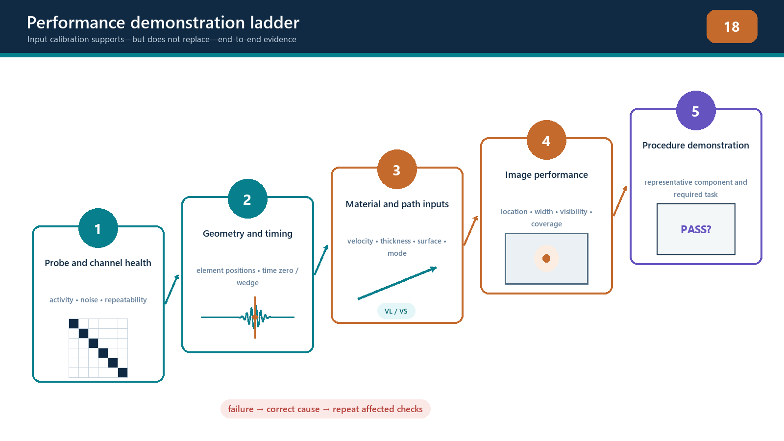
Advanced imaging needs several different forms of proof. An equipment check establishes that the instrument, probe and connected channels operate as expected. Setup verification confirms that geometry, timing, velocity, coordinates and reconstruction inputs place known reflectors correctly. Application performance demonstration shows whether the complete technique can perform its intended detection, location or sizing task under representative conditions.
These proofs must not be collapsed into one attractive reference image. Passing a channel check does not prove weld coverage. Locating one side-drilled hole does not prove crack-tip sizing. A phase-only coherence display may not need an amplitude reference for its colour scale, but the inspection still needs timing, position, coupling, model and application verification.
Learning outcomes
After completing this chapter, the learner will be able to:
distinguish calibration, standardisation, system verification, technique demonstration and qualification;
verify timing, velocity, wedge/element geometry, coordinate registration and encoder accuracy;
evaluate channel health and matrix completeness before and after acquisition;
demonstrate location, coverage, response stability and resolution across the qualified ROI;
define appropriate evidence for amplitude and phase/coherence outputs; and
document tolerances, corrective action and re-verification triggers.
Crossover map: from calibration echo to proof ladder
| Familiar UT/PAUT practice | Advanced-imaging requirement | Boundary |
|---|---|---|
| Set range and wedge delay on known reflectors. | Verify the complete element/wedge/surface time model and ROI registration. | One central reflector may not expose edge or multi-path error. |
| Check probe elements and sensitivity. | Audit transmit and receive patterns across the matrix and retained data. | Image appearance alone cannot identify every failed pair. |
| Calibrate an encoder over a known distance. | Verify zero, direction, scale, scan-axis assignment and position continuity in stored frames. | Displayed scan length does not prove absence of dropout or slip. |
| Establish reference amplitude and DAC/TCG. | Establish amplitude-TFM response controls where required and qualified. | Do not transfer amplitude rules to phase-only coherence. |
| Demonstrate PAUT coverage on reference reflectors. | Demonstrate each reported path/domain across the ROI and difficult orientations. | Equipment health is not application suitability. |
Use three separate proof gates
Gate A — equipment and complete-system health
Gate A asks whether the identified hardware and software are operating without unacceptable degradation. It covers the connected instrument, probe, wedge, cables, scanner interfaces and relevant software configuration. Typical checks include element activity, relative sensitivity, time-of-flight consistency, receiver noise, pulser/receiver behaviour, sampling, bandwidth, connectors, encoder response and file storage.
The check should expose both transmit and receive faults. A dead transmitter can degrade a matrix row; a failed receiver can affect a column; an isolated acquisition fault can affect one or several cells. A TFM image may still look smooth because thousands of remaining contributions hide the loss. Matrix inspection and channel evidence are therefore part of the check.
Passing Gate A means the system is operating within the defined health limits. It does not show that the chosen technique can detect or size the production discontinuity.
Gate B — setup and reconstruction verification
Gate B asks whether the controlled configuration maps known acoustic events to the correct time and component coordinates. Verify, as applicable:
probe, wedge and element map identity;
component velocity and thickness inputs;
wedge delay, element positions, index and separation;
surface or curvature model;
time origin, acquisition range and sampling;
encoder zero, direction, scale and axis assignment;
path labels, reflections, conversions and velocities;
ROI origin, bounds and grid;
aperture, pair selection and exclusions; and
reconstruction algorithm/version and image-domain controls.
Use targets at more than one depth and lateral position. A common timing offset can move all responses. A wrong velocity can produce increasing displacement with path length. A surface-model error may appear position-dependent. A single central target cannot distinguish all these causes.
For amplitude TFM, include checks for response stability as a target moves relative to the pixel grid, and for sensitivity or normalisation where the procedure uses amplitude. For phase/coherence output, verify repeatable position, detectability and expected response on suitable targets. Do not manufacture a dB equivalence or require a universal coherence value unless the controlled implementation and procedure establish it.
Gate C — application performance
Gate C asks whether the complete technique is capable of the assigned task on representative material and geometry. Targets should represent the required locations, orientations and acoustic behaviours. For a weld problem, this may include near-surface, mid-wall, backwall-adjacent, root/cap geometry, planar, tip-like and volumetric responses.
The demonstration should challenge:
the least favourable regions of each ROI;
direct, reflected and converted path families that will be reported;
planar/specular and diffracting behaviour;
near-surface and backwall limitations;
material attenuation, scattering and transfer conditions;
encoded coverage and scanner repeatability;
detection, location, separation and sizing where required; and
amplitude and phase/coherence outputs in their proper domains.
Application performance is established only within the demonstrated essential-variable range. A technique shown on a thin carbon-steel reference block is not automatically qualified for a thicker, curved, clad or coarse-grained production component.
Tolerances and reference values
Every check needs a documented expected result, tolerance, action on failure and record. Do not invent tolerances from the screen resolution or from habit. Use the governing procedure, controlled equipment standard, qualified technique or authorised technical decision.
A useful check record contains:
equipment and software identifiers;
reference block/specimen and target identifiers;
environmental condition where relevant;
exact configuration revision;
measured values and units;
stated tolerance and source;
pass/fail result;
corrective action;
repeated checks after correction; and
operator, date/time and reviewer.
Where a formal standard uses the terms calibration, standardisation or verification differently, follow the controlled organisation terminology. The essential distinction is functional: equipment health, setup accuracy and application performance answer different questions.
Encoder and position verification
Calibrate the encoder over a representative distance using an independent length reference. Verify positive direction, zero, units, scale and return behaviour. For multi-axis scans, verify axis assignment and the sign of each axis. A reversed sign can mirror the component map while leaving local image geometry apparently plausible.
Run a short encoded trial at the intended speed. Compare commanded/physical travel with stored start and end positions. Look for repeated positions, missing frames, abrupt jumps and disagreement between direction of motion and recorded sign. Confirm that the instrument flags dropped acquisition where applicable; absence of an alarm is not proof that the dataset is complete.
Amplitude-domain checks
Amplitude TFM still depends on linear, unsaturated raw signals. Establish the required gain/reference condition and verify response behaviour across the relevant ROI. If normalisation or a sensitivity map is used, record its derivation, applicable path and limits. Applying a map generated for another probe, path, thickness or software version can create false uniformity.
Grid-related amplitude stability should be checked by translating a known reflector relative to the grid or by a controlled equivalent method. A coarse grid can sample different parts of an oscillatory point-spread response and vary the reported peak. The acceptable variation and test method come from the approved technique, not from a universal pixels-per-wavelength claim.
Phase/coherence-domain checks
Phase-only processing changes what is displayed, not the need for system evidence. Checks should confirm:
raw channel data are above noise and below clipping;
timing, velocity, surface and path models align the phases correctly;
expected target types are detected at required locations;
reported coordinates are repeatable;
planar and diffracting target behaviour is understood;
coupling loss remains independently detectable;
thresholds and processing settings are controlled; and
the same configuration can reproduce the reference result.
A low coherence response may mean absent reflector, unfavourable scattering, poor signal, model error or implementation behaviour. A high response may arise from a crack tip, a small scatterer, coherent geometry or cross-talk. Calibration evidence narrows these possibilities; it does not make the image self-interpreting.
Frequency and triggers for re-verification
The controlled procedure defines pre-use, periodic, interruption, post-use and change-triggered checks. Typical triggers include:
probe/wedge replacement, disconnection, damage or excessive wear;
instrument, cable, scanner or encoder change;
significant temperature change;
material, thickness or surface outside the demonstrated range;
gain, sampling, filter, matrix or aperture change;
velocity, geometry, path, ROI or grid change;
software, firmware or algorithm update;
dropped data, coupling failure or unexpected reference response; and
elapsed time or shift limit defined by procedure.
When a post-scan check fails, quarantine the affected data. Establish the last valid check, investigate the cause and follow the approved disposition. The response may require rescanning, reprocessing from retained raw data, technical review or report amendment. Do not simply recalibrate and continue as if the earlier data remained valid.
Field workflow: witnessed check and release
Confirm the controlled instruction, equipment list, setup/reconstruction revision and target record.
Inspect probe, wedge, cables, scanner and reference specimen.
Complete Gate A health checks and matrix/channel audit.
Establish timing, velocity, coordinate and encoder inputs.
Reconstruct known targets using every reported path and image domain.
Compare measured location, response and separation with stated tolerances.
Demonstrate the complete technique on representative targets where required.
Record failures and correct one cause at a time.
Repeat the failed check and every dependent check.
Lock the released configuration and retain the reference dataset.
Practical 12 — Detect and correct a controlled configuration error
Aim
Complete a witnessed equipment/setup/performance record, identify one introduced error and restore the system without hiding the cause.
Resources
identified array instrument, probe, wedge and encoder;
controlled reference specimen containing targets at several positions;
approved check record with stated tolerances;
known-good acquisition and reconstruction configuration; and
instructor-controlled error card.
Method
Verify hardware, software and reference-target identities.
Complete the required element, matrix, noise and timing health checks.
Calibrate encoder distance, sign and zero.
Reconstruct known targets in the required amplitude and/or coherence views.
Record coordinates, response behaviour and any separation metric required by the controlled record.
Receive a configuration containing one error, such as wrong velocity, wedge offset, surface origin, inactive receiver, reversed encoder direction or altered grid.
Compare the evidence with the known-good record and list at least two hypotheses.
Perform a discriminating check without changing multiple variables.
Identify the root cause, restore the controlled value and repeat all affected checks.
State which production data would be affected if the fault were found after scanning.
Evidence to retain
completed health, setup and performance record;
channel/matrix evidence;
encoder calculation and trial trace;
before/error/corrected images with identical display controls;
measured coordinates and tolerances;
root-cause reasoning and corrective action; and
witness signature and released revision.
Stop rules
Stop if a required tolerance or target identity is missing; raw data are clipped or noise-dominated; a channel fault is hidden by the reconstruction; encoder direction cannot be proven; the error cannot be isolated; or correction requires a change outside the qualified range. Quarantine any production data associated with a failed post-use check until authorised disposition.
Common traps
Calling one reference image “calibration” for the entire technique.
Passing equipment health and claiming application suitability.
Checking only the diagonal FMC traces.
Correcting a displaced reflector by moving the ROI rather than fixing the model.
Inventing a dB relationship for phase-only coherence.
Demonstrating only favourable point targets.
Ignoring encoder sign and continuity because total distance looks correct.
Changing several parameters before identifying the root cause.
Failing to repeat dependent checks after correction.
Continuing production scanning after a failed check without disposition.
Chapter summary
Equipment health, setup verification and application performance are separate gates. The first confirms system operation, the second checks the travel-time and coordinate model, and the third demonstrates the complete technique against the actual task. Amplitude and phase/coherence outputs require different response-domain checks, while both depend on valid signals, timing, geometry, coupling, position and controlled processing.
Every check requires a tolerance, source, result and action on failure. Correct the cause, repeat affected checks and quarantine questionable data. Passing a polished reference image is not a shortcut through the proof ladder.
Study and revision only. This is not an approved inspection procedure, acceptance criterion or qualification.