
CHAPTER 5 · Ultrasonics Level 1
The Probe, Couplant and Instrument Chain
In this chapter · 18 sections
Why this matters
The screen shows an electrical signal, but the job concerns sound inside a component. Between those two things sits a complete chain: pulser, cable, probe, protective layers, couplant, material, reflector, receiver, processing and display. A change anywhere in that chain can alter the A-scan. This chapter opens the probe in a simple way, compares common probe arrangements and explains why coupling, cables, settings, wear and temperature must be treated as measurement variables.
What you already need
- A probe sends a pulse and receives an echo.
- Interfaces can reflect and transmit different parts of the sound.
- Frequency, wavelength, bandwidth and pulse length are different quantities.
- A displayed amplitude is not a direct reflector-size measurement.
What you will learn
- Follow the complete transmit-and-receive signal chain.
- Explain how a piezoelectric element changes electrical and mechanical energy.
- Compare common straight, angle, dual, delay-line and immersion probes.
- Describe how coupling, cable and receiver settings change response.
- Explain aperture, focus and the two-way pulse-echo field.
- Select and check a probe-system arrangement for a simple task.
Words you will meet
- Transducer: device that converts energy from one form to another.
- Piezoelectric: able to link electrical voltage with mechanical strain.
- Damping: control that reduces continued ringing after excitation.
- Aperture: active area used to send or receive sound.
- Focus: region where the field is deliberately concentrated.
5.1 Follow the complete signal path
Pressing the TEST button does not place a finished A-scan inside the steel. The system performs a chain of energy changes.
On transmission:
- The instrument pulser creates a short electrical excitation.
- The cable carries that excitation to the probe.
- The active element changes electrical energy into mechanical vibration.
- Probe layers, a delay line or a wedge shape and transmit the vibration.
- Couplant carries pressure across the small gap at the component surface.
- The ultrasonic field travels through the component.
On reception, part of the journey reverses:
- Returning sound reaches the probe.
- The active element changes mechanical vibration into a small voltage.
- The cable carries the voltage to the receiver.
- Electronics amplify and filter it.
- A digitiser records samples.
- Software turns selected information into an A-scan or measurement.
The following figure lays out that chain. Notice that the displayed response is several transformations away from the physical interaction.
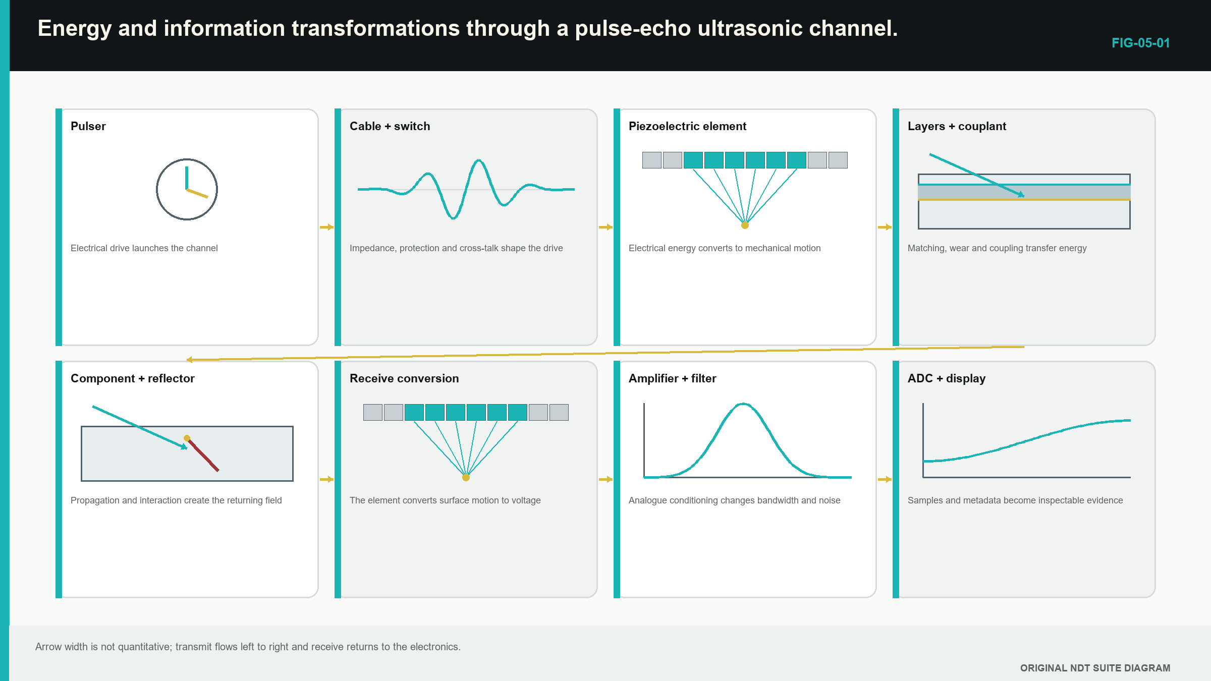
Every link adds delay, loss and a limited frequency range. Every link can also add noise or distortion. Changing the cable, probe, wedge, filter or receiver load changes the complete response even when the probe label still says the same frequency. National Institute of Standards and Technology (NIST) reference-block research records differences among nominally similar transducers and the effects of frequency response, damping, construction and electrical loading. [R010]
This is why the complete connected arrangement is checked. A probe that worked yesterday can produce a visible echo today while its pulse shape, angle or sensitivity has changed enough to matter.
5.2 How a piezoelectric probe makes a pulse
Most common NDT probes use a piezoelectric active material. Apply a voltage and the material changes shape slightly. Squeeze or stretch it and it produces electrical charge. The same active element can therefore send and receive.
The element does not work alone. A basic probe stack can contain:
- an active piezoelectric element;
- backing behind the element;
- one or more matching layers in front;
- a protective wear face;
- electrical connections, housing and shielding;
- a delay line or wedge where the probe design needs one.
The active element tends to vibrate strongly near certain resonant frequencies. Backing absorbs energy from the rear and helps the element stop ringing. Stronger damping normally shortens the pulse and broadens the frequency range. Matching layers improve energy transfer between materials with very different impedance. The wear face protects the stack but also adds its own delay and frequency effect.
The main response band is commonly described by a centre frequency and bandwidth. Bandwidth is the difference between an upper and lower stated cutoff. Fractional bandwidth compares that width with the centre frequency. In words:
fractional bandwidth = usable frequency width ÷ centre frequency
| (5.1) Fractional bandwidth · EQ-05-01 Where: BW_fraction = fractional bandwidth; f_high = upper stated cutoff (Hz); f_low = lower stated cutoff (Hz); f_center = declared centre frequency (Hz) Model limits: cutoffs use the same stated amplitude convention and the response has a meaningful main band |
|---|
The cutoff convention must be stated. Two bandwidth numbers based on different amplitude levels are not directly comparable.
Piezoelectric ceramics can give strong conversion but are dense and brittle. Piezocomposites mix active ceramic with polymer to control impedance, modes and bandwidth. Special single-crystal materials can give high coupling. Flexible polymer films can fit unusual shapes but often provide lower conversion efficiency. The complete construction and load matter more than one material name.
At a deeper level, the probe is a linked electrical and mechanical resonant network. Cable capacitance and receiver impedance can change its damping. Contact with a wedge, water or component changes its acoustic load. Engineering Ultrasonics develops equivalent-circuit models; Level 1 needs the practical result: probe, cable and material behave together.
5.3 Common probe arrangements
A straight-beam contact probe sends a mainly normal longitudinal field into the component. It is widely used for plate laminations, forgings and thickness work where the intended path is roughly square to the surface.
An angle-beam probe uses a wedge. The wedge delays, refracts and commonly mode-converts the pulse into a shear wave. It is useful for weld and planar-reflector orientations that a straight beam cannot meet effectively.
A dual-element probe has separate transmitting and receiving elements. They are usually tilted so their fields overlap below the surface. Separation reduces some transmit-recovery interference and can improve selected near-surface thickness measurements. The crossed path is not a simple straight line and can make time-to-thickness conversion nonlinear.
A delay-line probe adds a known material path between the active element and component. This protects the element, moves the component echoes away from the initial pulse and can support hot or thin-part measurements when designed for the condition.
An immersion probe sends sound through a controlled water path. It avoids changing hand pressure and supports accurate scanning. It also adds a water-interface echo, alignment needs, water-path multiples and temperature effects.
A focused probe concentrates the field over a region. The region has finite length and width; it is not one perfect point. A focused probe can improve local sensitivity or resolution but becomes more sensitive to stand-off, surface shape and target position.
Through-transmission places a transmitter and receiver on opposite sides. It responds to changes in sound reaching the receiver but provides limited direct depth information. Pitch-catch uses separated probes on the same or different surfaces. Tandem arrangements use a planned multi-leg path. No arrangement is best in every situation.
| Worked example · Choosing a first probe for two thickness tasks WE-05-01 Given: One task is a smooth 50 mm plate. Another is rough corroded wall expected to be 3–8 mm thick. Only one side is accessible. Find: A reasoned starting probe arrangement for each task. Steps: Compare near-surface recovery, pulse overlap, surface condition, intended thickness range and need for a clear back wall. Answer: A conventional single-element straight-beam probe is a sensible starting point for the smooth thick plate because the back-wall echo is well separated in time. A suitably selected dual-element probe can be a better starting point for thin corroded wall because the separate elements reduce some early recovery interference and their fields overlap in a shallow region. What this tells you: Probe family is chosen from the task, not from a memorised application label. Both choices still need reference checks over the intended range and surface condition. Common mistake: Assuming a dual probe is automatically accurate at every shallow and deep value because it is sold for corrosion work. |
|---|
5.4 Coupling and surface contact
Couplant fills much of the air gap between probe and component. Its film thickness, wetting, viscosity and temperature affect transmission. Surface roughness and curvature affect the contact footprint and local incident angles. Probe pressure can change all of these.
Stable coupling matters for detection. It matters even more when amplitudes are compared. If all echoes rise and fall together as the probe rocks, a common coupling change is plausible. If one response changes while the back wall remains steady, target direction or local field becomes more likely.
Coupling can scale most of the waveform, but it can also change frequency content. A rough surface may pass low frequencies more consistently than high frequencies. Curvature can redirect the field. A smooth reference block may therefore produce a different transfer from the component.
Repeated remounting estimates practical repeatability. Suppose ten placements vary by about 2 dB. A 1 dB difference between two target readings is then weak evidence of a real target change. If placements vary by only 0.2 dB, the same difference is more meaningful. Repeatability does not prove accuracy, but it shows the response differences the arrangement can reliably separate.
Immersion changes the contact problem rather than removing it. Water-path length, alignment, bubbles and water temperature become controlled variables. A calculated stand-off is only a starting point; the field and interface echoes must still be checked.
5.5 Cables, receiver controls and noise
The cable carries a high-voltage transmit pulse and later carries a small received voltage. Its length, capacitance, shielding, impedance and connector condition can change pulse shape, bandwidth, recovery and noise. A cable substitution can restore peak height after a gain change while still losing useful high-frequency content.
Pulser energy, electrical damping, gain and filtering interact. More excitation or gain can make a weak response visible until ringing, noise or saturation becomes dominant. Filtering can make a trace look calmer, but it can remove useful frequency content, lengthen the pulse or shift phase.
Noise can come from several places:
- receiver electronics;
- electromagnetic pickup and poor shielding;
- cable or connector movement;
- probe vibration and internal condition;
- unstable coupling;
- real material scattering.
Tests can include selected parts of the chain. A receiver terminated without a probe checks some electronics. A connected probe in air adds cable and probe electrical behaviour. Coupling it to a clean reference adds the acoustic path and target. Coupling to the component adds the real material and surface. Each comparison answers a different question.
The receiving element and cable form a frequency-dependent electrical load. A long cable may reduce bandwidth or increase interference pickup. A higher screen gain can restore displayed height, but it cannot restore lost pulse shape or information.
5.6 Aperture, focus and simple beam extent
The active probe area is its aperture. A larger circular aperture generally creates a narrower far field and a longer, more complicated near field. A smaller aperture spreads more widely. The actual result also depends on wavelength, shape, focusing and load.
Focusing concentrates energy over a finite region. Within that region, response can be stronger and the beam can be narrower. Away from it, performance changes. A focus suitable for a local pit may be less robust over a wide depth range.
At Level 1, treat the drawn central ray as a direction guide and the real beam as a region around it. Moving the probe across a small known reflector helps reveal where response is strongest and how quickly it falls. A flat reflector may respond over a narrow movement range, while a rounded target may respond over a broader one.
A larger aperture is not automatically better. Its narrower field can help direction and local response, but its larger contact face may be awkward on a curved or rough surface. A smaller probe can make better contact and spread more widely, though its local response and direction control may be lower.
| Worked example · Estimating pulse length from probe ringing WE-05-02 Given: A 5 MHz probe produces about 3.5 effective cycles in steel represented by a longitudinal speed of 5,900 m/s. Find: Approximate spatial pulse length. Steps: First find wavelength. lambda = 5,900/(5 x 10^6) = 1.18 mm Then multiply by effective cycle count. SPL = 3.5(1.18) = 4.13 mm Answer: Approximate spatial pulse length is 4.1 mm. What this tells you: Close reflectors along the beam may produce overlapping responses. The exact separation limit also depends on bandwidth, amplitude ratio, noise and measurement rule. Common mistake: Treating 4.1 mm as a universal minimum reflector spacing for every target and threshold. |
|---|
Step up preview - the outgoing and returning field
Pulse-echo response requires sound to reach the target and then return into the receiving probe. Pitch-catch needs overlap between separate transmit and receive paths. Level 2 develops the formal two-way field and contour consequences; Level 1 retains only this physical reminder and does not assess field-product mathematics.
5.7 Temperature, wear and fault tracing
Wedge and delay-line speed change with temperature. That shifts apparent zero and, for angle-beam probes, can change refracted angle. Couplant viscosity changes. Piezoelectric sensitivity and matching layers can drift. Excessive heat can damage or depolarise the active material.
Wear changes wedge thickness, contact shape, probe index and incident angle. A cracked wear face can add reverberation. A damaged internal bond can create an extra resonance. The probe may still produce an echo while its field has become unsuitable.
Condition checks should therefore look at task-relevant features. Timing checks can reveal delay change. Response comparisons can reveal sensitivity change. Pulse shape and spectrum can reveal bandwidth change. A field or angle check can reveal geometry change. One alive/dead echo is only one layer of evidence.
| Worked example · Tracing a bandwidth change through the chain WE-05-03 Given: A reference echo falls by 4 dB and loses high-frequency content after a cable replacement. The original probe on the original cable reproduces its baseline. The same probe on the replacement cable reproduces the loss. Receiver settings and target are unchanged. Find: The leading cause category. Steps: Compare what changed. Probe, target and receiver settings are held. The response follows the replacement cable. Answer: Cable loading or cable integrity is the leading cause. What this tells you: Adding gain may restore peak height but cannot restore the lost bandwidth or original pulse shape. The cable should be compared using the information needed by the task. Common mistake: Blaming the component because the changed trace was first noticed while scanning it. |
|---|
In a linear reciprocal system, swapping transmitter and receiver should produce related transfer behaviour. This is called reciprocity. Practical channel differences, electronics and coupling can prevent perfect symmetry. Level 1 uses reciprocity as a diagnostic expectation, not as permission to invent missing data.
5.8 Selecting an information-producing system
Probe selection balances several needs:
- enough penetration through the material;
- pulse length and beam width suitable for required separation;
- a direction that can interact with the target;
- stable contact on the available surface;
- a useful depth or focus range;
- tolerance of temperature, curvature and wear;
- a signal that the instrument can receive without saturation.
Changing one feature usually changes another. Higher frequency shortens wavelength but can increase material loss. A larger aperture narrows part of the field but expands the contact footprint. Strong damping shortens the pulse but can reduce peak response. Focusing improves one region but reduces depth tolerance.
The chosen system is therefore a starting hypothesis. It should be challenged on a reference or representative specimen that exposes its expected weakness. A probe for thin wall should be checked near the lower thickness limit. A probe for a coarse casting should be checked over the long noisy path. An angle-beam system should be checked for the required directions and volume.
The selection record should identify the complete connected system, not only the probe model. Cables, wedge, instrument settings, couplant, temperature range and reference evidence belong to that identity.
Probe families and pulse-echo signal-chain concepts in this chapter align with the international ultrasonic training foundation used through Part I. [R001]
In plain words
- The displayed echo is the result of a complete electrical, mechanical and digital chain.
- A piezoelectric element changes electrical energy into vibration and returning vibration into voltage.
- Backing, matching layers and wear faces control pulse shape and transfer.
- Different probe families solve different access, depth and recovery problems.
- Coupling, cable and receiver settings can change a response without any component change.
- Aperture and focus describe a field region, not one perfect ray or point.
- Pulse-echo sensitivity depends on both the outgoing and returning field.
- Probe suitability must be checked over the real task range and conditions.
Key terms
- Transducer: device that converts energy between forms.
- Piezoelectric: linking electrical field and mechanical strain.
- Damping: reduction of continued ringing.
- Aperture: active transmitting or receiving area.
- Focus: finite region where the field is concentrated.
- Reciprocity: expected related behaviour when transmit and receive positions are exchanged in a suitable linear system.
Key relationships
- BW_fraction = (f_high-f_low)/f_center: fractional bandwidth compares the stated useful frequency width with centre frequency.
- SPL = n lambda: effective pulse length increases with ringing cycle count.
Common mix-ups
- Nominally identical probe labels do not guarantee identical response.
- Higher frequency is not automatically more sensitive.
- Gain cannot restore lost bandwidth or physical resolution.
- A focused probe is not focused at every depth.
- Couplant improves transmission but does not erase roughness or curvature.
Bridge to Chapter 6
This chapter followed the signal from pulser to component and back. Chapter 6 concentrates on the A-scan that appears at the end of that chain. It explains axes, range, zero, gain, gates, common false responses and the use of timing and movement to identify echoes.
Sources and further study
- [R001]
- [R010]
Study and revision only. This is not an approved inspection procedure, acceptance criterion or qualification.